Eureka AIR delivers breakthrough ideas for toughest innovation challenges, trusted by R&D personnel around the world.

Shock proof structure of battery pack for receiving battery cell

a battery cell and shock-proof technology, which is applied in the direction of battery isolation, cell components, electrical equipment, etc., can solve the problems of easy damage unsatisfactory, and easy shock or collision to the battery cell, and achieve the effect of simplifying the structure and upgrading the stability of holding the battery cell

Inactive Publication Date: 2012-10-04
DE POAN PNEUMATIC
View PDF0 Cites 818 Cited by
  • Summary
  • Abstract
  • Description
  • Claims
  • Application Information

AI Technical Summary

Benefits of technology

[0007]The present invention provides a shock proof structure of a battery pack for receiving a batter cell, which comprises shock absorbance to firmly hold the battery cell within the battery pack, as well as provides a simplified structure of the shock proof structure of the battery pack and upgrades the stability of holding the battery cell within the battery pack.
[0010]According to the above depiction, the support arm of the plate has elasticity provided by the arm and the bent portion, and the stretchable gap helps to increase the stretching ability. Thus the ability for shock proof and holding effect of the battery cells between the first and the second buckling portions can be increased, and also the shock proof structure of battery pack may be simplified and upgrade the stability of holding the battery cell within the battery pack.
[0014]The pad fills in the buffering space through the through groove to increase the elasticity of the support arm and the arm.

Problems solved by technology

Serious shock or collision may easily occur to the battery cell when the electrical tool is under impact or dropped on the ground and cause damage to the battery cell.
However, the result is not ideal.
The latter prior art has a complex structure of an inner plates that increases the manufacturing cost.
However, the stretching limitation of the inner plates limits the shock absorbing ability.

Method used


Image

  • Shock proof structure of battery pack for receiving battery cell
  • Shock proof structure of battery pack for receiving battery cell
  • Shock proof structure of battery pack for receiving battery cell

Examples


Embodiment Construction

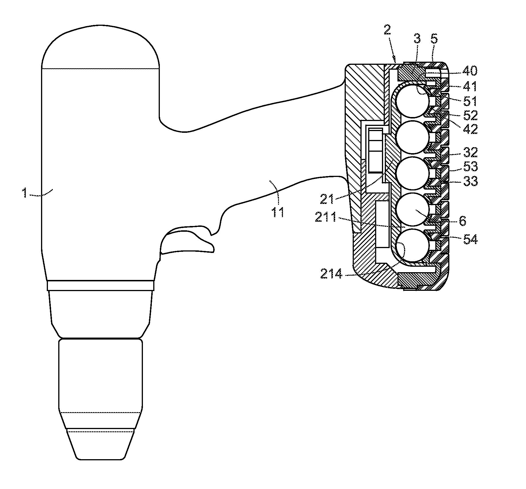
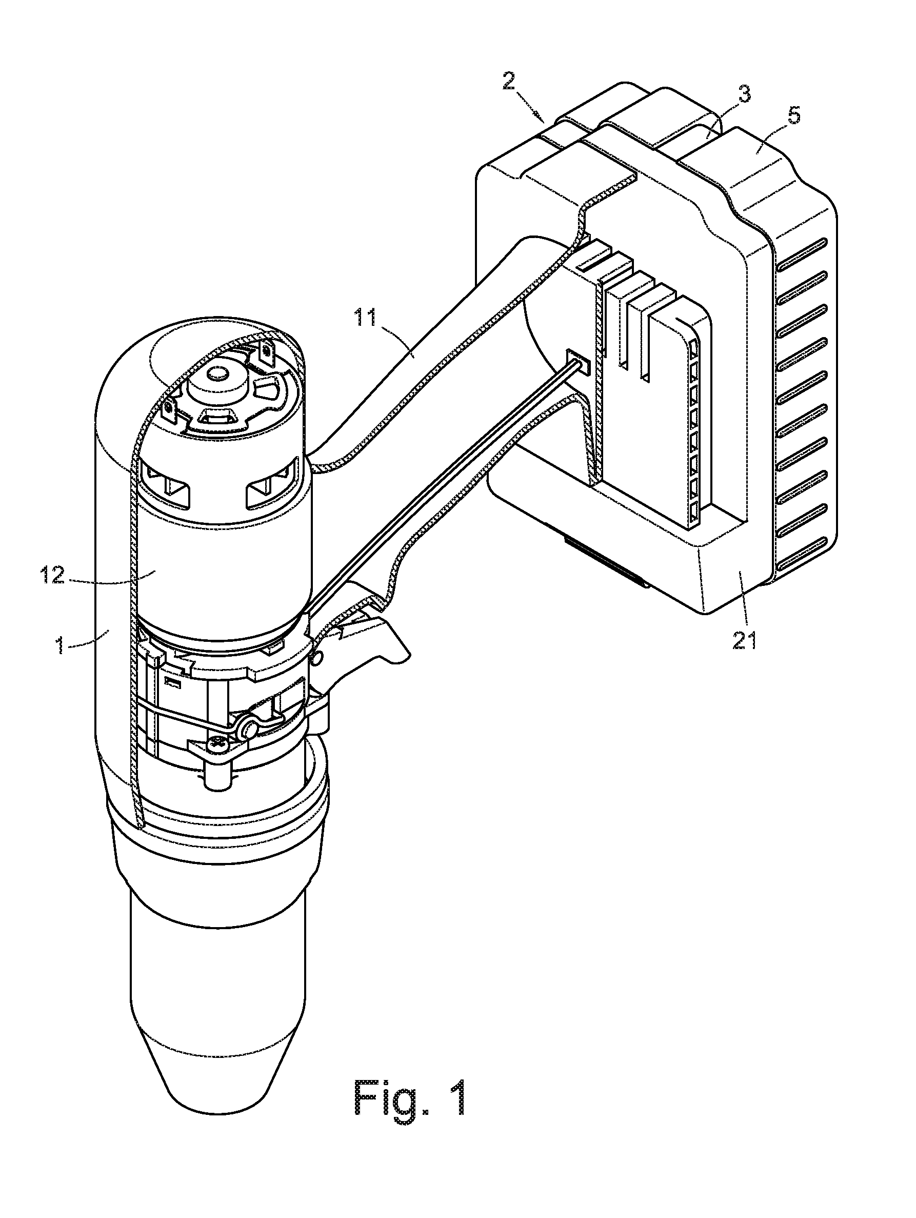
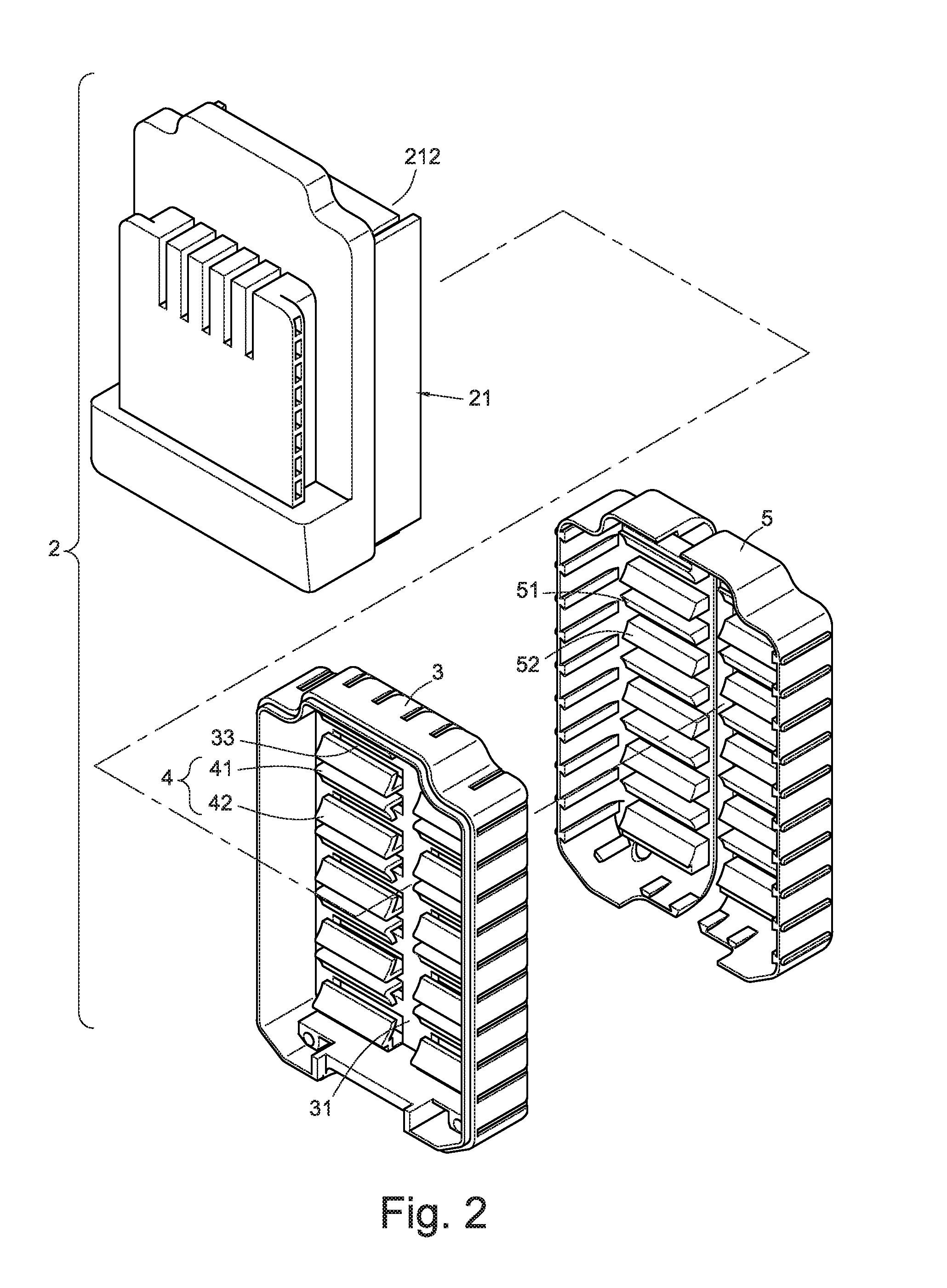
[0028]Referring to FIGS. 1 and 5, a shock proof structure of a battery pack 2 for receiving a battery cell is disclosed. The battery pack 2 comprises a base 21 inlayed at a distal end of a handle 11 of an electrical tool 1. The electrical tool 1 can be an electrical screw gun, an electrical staple gun, an electrical screw driver, an electrical driller, an electrical impact wrench and so on. Taking the electrical screw gun as an example in the embodiment of the present invention, the base 21 comprises a space 211 for receiving the battery cell (referring to FIG. 6) and connected with a lid 3 for opening or closing the space 211. A plurality of buckling portions 214 with gap between one another are formed at the bottom 213 of the space 211 (referring to FIG. 8). The first buckling portion 214 in the embodiment can be an arch shape. The power supplied by the battery cell 2 can be transmitted through the handle 11 to the electrical tool for driving the motor 12.

[0029]Accordingly, a plur...


PUM

PropertyMeasurementUnit
stretching gapaaaaaaaaaa
acute angleaaaaaaaaaa
distanceaaaaaaaaaa

Abstract

A shock proof structure of a battery pack for receiving a battery cell is formed in an electrical tool. The battery pack includes a base having a space for receiving the battery cell and a lid for opening or closing the space. The space has a plurality of first buckling portions separated by a gap disposed at a bottom side thereof. A plurality of second buckling portions with shock absorbance is formed at an inner sidewall of the lid. The plate sets include two plates separated by a gap are symmetrically positioned. The plates of each plate set have a second buckling portion with a stretching gap formed in between. The second buckling portion is positioned at the opposite end of the first buckling portion to provide the battery cell to be steadily buckled between the first and the second buckling portions.

Description

BACKGROUND[0001]1. Technical Field[0002]The present invention relates to a shock proof structure of a battery pack for receiving a battery cell. More particularly, the present invention relates to a space formed in a base of a battery pack for receiving a battery cell; especially to a lid for opening or closing the space, as well as shock proof plates on the lid.[0003]2. Related Art[0004]An electrical tool, for example, electrical screw gun, electrical nail gun, electrical screwdriver, electrical driller, electrical wrench, etc, can be driven by a portable battery pack allowing users to use indoor / outdoor anywhere away from the power socket. Conventional battery pack is disposed at a distal end of an electrical tool including a space formed at a side of the base thereof to receive a battery cell, and comprises a lid that opens or closes the space. The battery cell is generally formed in a cylinder shape. Serious shock or collision may easily occur to the battery cell when the electr...

Claims


Application Information

Patent Timeline
Patent Type & Authority Applications(United States)
IPC IPC(8): H01M2/10B25F5/02
CPCB25F5/006H01M2/1094H01M2/1055Y02E60/10H01M50/213H01M50/24
Inventor LIANG, CHIA-SHENGTSENG, CHU-HSIANG
Owner DE POAN PNEUMATIC
Why Eureka
Eureka Blog
Learn More