Endoscope air-supply system

a technology of air supply system and endoscope, which is applied in the field of endoscope air supply system, can solve the problem of inability to accurately measure the gas pressure in the lumen

Inactive Publication Date: 2012-10-04
FUJIFILM CORP +1
View PDF6 Cites 13 Cited by
  • Summary
  • Abstract
  • Description
  • Claims
  • Application Information

AI Technical Summary

Benefits of technology

[0038]As described above, according to the present invention, intraluminal pressure can be precisely measured, thereby performing air supply so as to keep an appropriate pressure, and when an endoscope is inserted into a lumen to perform observation or treatment, an operator does not need to perform frequent operation of inflating the lumen.

Problems solved by technology

Conventionally, however, an operator operates an air-supply button manually to supply gas to the lumen, and there is the problem that the operator needs to operate the air-supply button frequently in order to inflate the lumen and keep the pressure in the lumen constant.
Further, it is necessary to measure the gas pressure in the lumen in order to keep the gas pressure in the lumen appropriate, but there is the problem that attachment of body fluid to the air-supply duct communicating with the pressure sensor, in particular to an opening portion thereof, makes it impossible to measure the gas pressure in the lumen correctly.

Method used


Image

  • Endoscope air-supply system
  • Endoscope air-supply system
  • Endoscope air-supply system

Examples


first embodiment

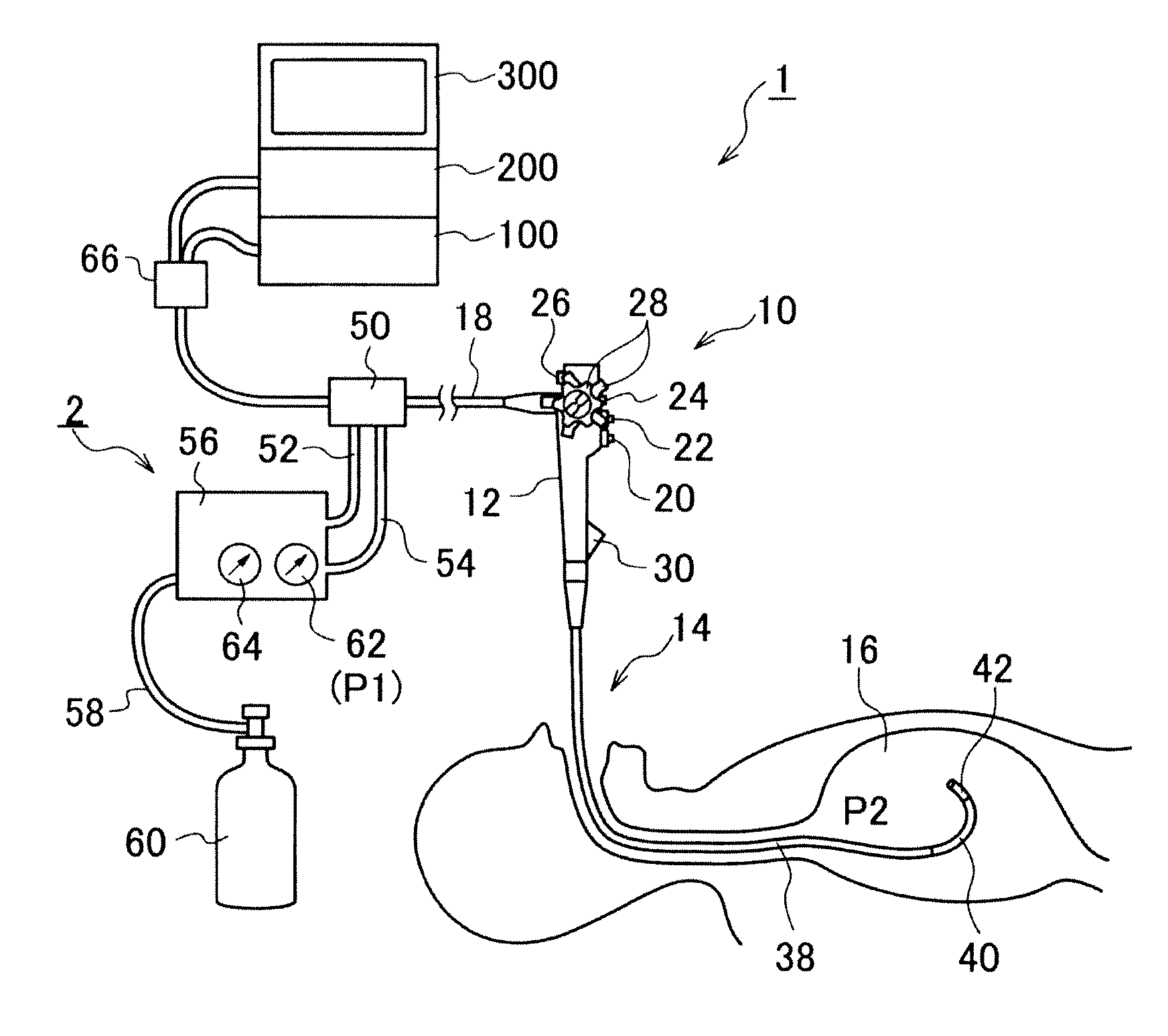
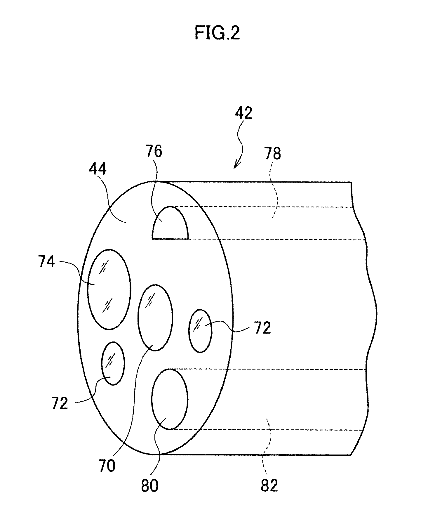
[0049]FIG. 1 is a configuration diagram showing the outline of an endoscopic system provided with an endoscope air-supply system according to the present invention.

[0050]As shown in FIG. 1, an endoscopic system 1 is provided with an endoscope air-supply system 2. The endoscopic system 1 is mainly composed of an endoscope (flexible endoscope) 10, an endoscope air-supply system 2, a light source device 100, an endoscope processor 200, and a monitor device (display device) 300.

[0051]The endoscope 10 is provided with a hand operation part 12 and an insertion part 14 provided so as to be continuous with the hand operation part 12. An operator grasps the hand operation part 12 disposed on a proximal end side of the endoscope 10 to operate the endoscope 10, and inserts a distal end side of the insertion part 14 into a lumen of a subject, such as a stomach 16, to perform observation, diagnosis, or curative treatment.

[0052]The hand operation part 12 is connected with a universal cable 18, an...

second embodiment

[0102]FIG. 7 is a configuration diagram showing the outline of an endoscopic system provided with an endoscope air-supply system according to the present invention.

[0103]In FIG. 7, similar components to those in the first embodiment shown in FIG. 1 are denoted by identical reference signs. As shown in FIG. 7, in the second embodiment, separately from the tube for constant-pressure air supply 54, a duct dedicated to pressure measurement (duct for pressure measurement) 53 is drawn from the air-supply device 56, and inserted into the lumen along the endoscope insertion part 14 so that the pressure in the lumen is measured through the duct for pressure measurement 53.

[0104]FIG. 8 is a configuration diagram showing the outline of an air-supply device 56 of the second embodiment.

[0105]As shown in FIG. 8, the duct for pressure measurement 53 is connected to a decompression part 87, and the decompression part 87 is connected to a carbon dioxide gas cylinder 60 through a high-pressure connec...


PUM


Abstract

An endoscope air-supply system comprising: a gas supply device which supplies predetermined gas to a lumen of a subject through an air-supply duct; a pressure measurement device which measures pressure in the lumen and which is connected through a duct for pressure measurement communicating with the lumen; a flushing device which supplies gas for flushing to the duct for pressure measurement; and an instruction device which instructs the pressure measurement device to perform pressure measurement and which instructs the flushing device to supply the gas for flushing in synchronism with the pressure measurement by the pressure measurement device.

Description

BACKGROUND OF THE INVENTION[0001]1. Field of the Invention[0002]The present invention relates to an endoscope air-supply system, and in particular to an endoscope air-supply system to supply constant-pressure gas from an air-supply device into a lumen of a subject through an opening provided at a distal end portion of a flexible endoscope inserted into the lumen to perform observation or treatment of the lumen.[0003]2. Description of the Related Art[0004]Conventionally, in the field of medicine, medical diagnosis utilizing an endoscope is widely performed, in particular, an image of a lumen of a subject is taken by a built-in imaging device, such a CCD, at an inserted distal end of an endoscope inserted in the lumen, and signals for the image are subjected to processing by a processor and the processed image is displayed on a monitor so that a doctor can observe the image to use the image for diagnosis or to insert a treatment instrument through a channel for treatment instrument pa...

Claims


Application Information

Patent Timeline
Patent Type & Authority Applications(United States)
IPC IPC(8): A61B1/015
CPCA61B1/015A61M13/003A61B1/32A61B1/126
Inventor TORISAWA, NOBUYUKINAKAJIMA, KIYOKAZU
Owner FUJIFILM CORP
Why Eureka
Try Eureka