Computer system and computer system management method

a computer system and management method technology, applied in computing, instruments, electric digital data processing, etc., can solve the problems of insufficient apparatus capacity, end of the service life of the apparatus, and drop in the performance of the apparatus, so as to reduce the management load

Active Publication Date: 2012-10-04
HITACHI LTD
View PDF5 Cites 81 Cited by
  • Summary
  • Abstract
  • Description
  • Claims
  • Application Information

AI Technical Summary

Benefits of technology

[0038]With the foregoing in mind, an object of the present invention is to provide a computer system and a computer system management method that is able to reduce the management load.

Problems solved by technology

For example, drops in apparatus performance, the end of an apparatus' service life, insufficient apparatus capacity, a dearth of network bandwidth, and system expansion will result in a data center replacing a server, network apparatus or storage apparatus with a new apparatus, adding a new apparatus, or removing an old apparatus from the computer system.
Therefore, there is a limit on the number of domain switches that can be disposed in a single fabric.
LU granular access control is not possible with zoning since access control is in FC port units.

Method used


Image

  • Computer system and computer system management method
  • Computer system and computer system management method
  • Computer system and computer system management method

Examples


example 1

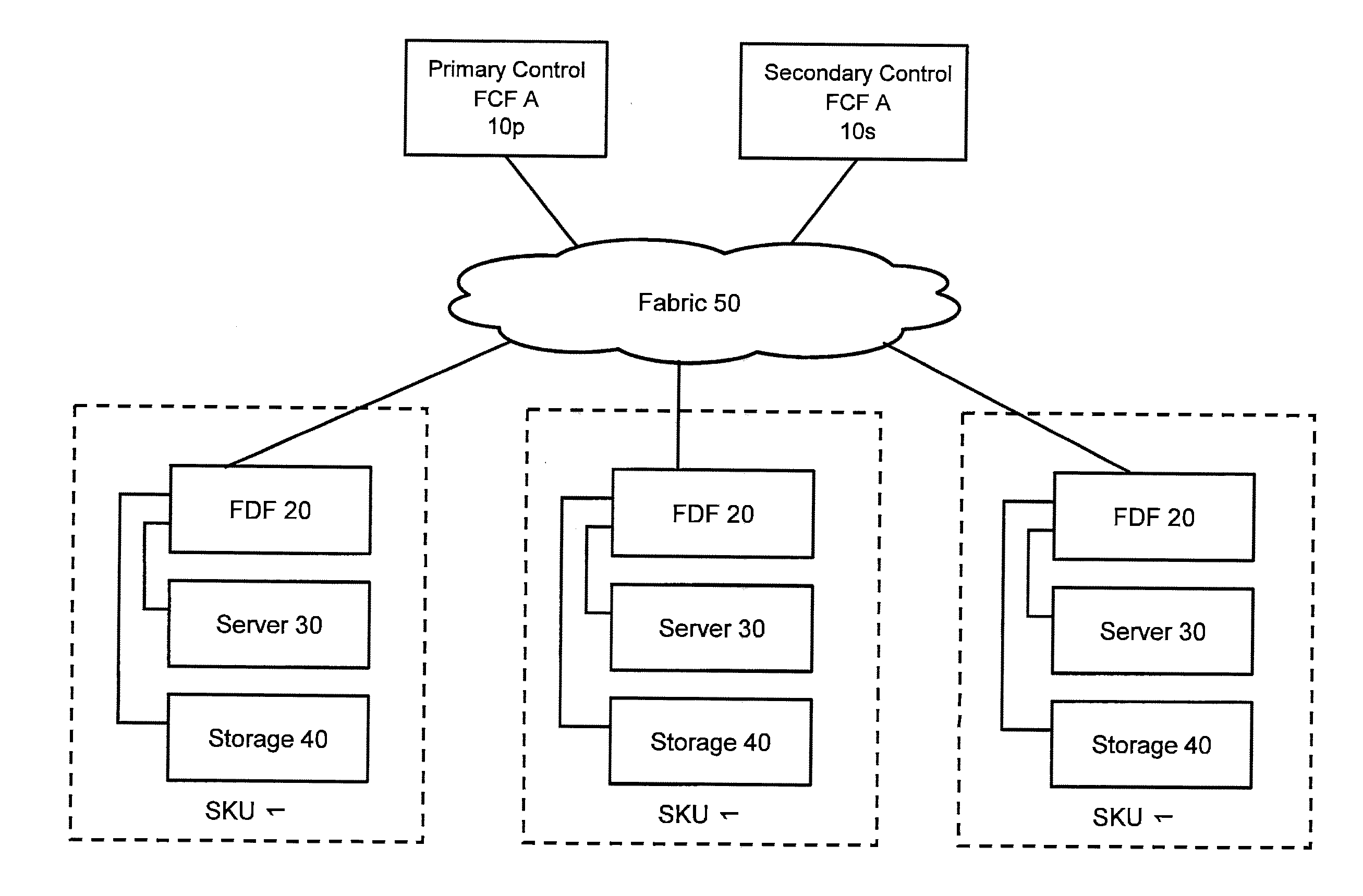
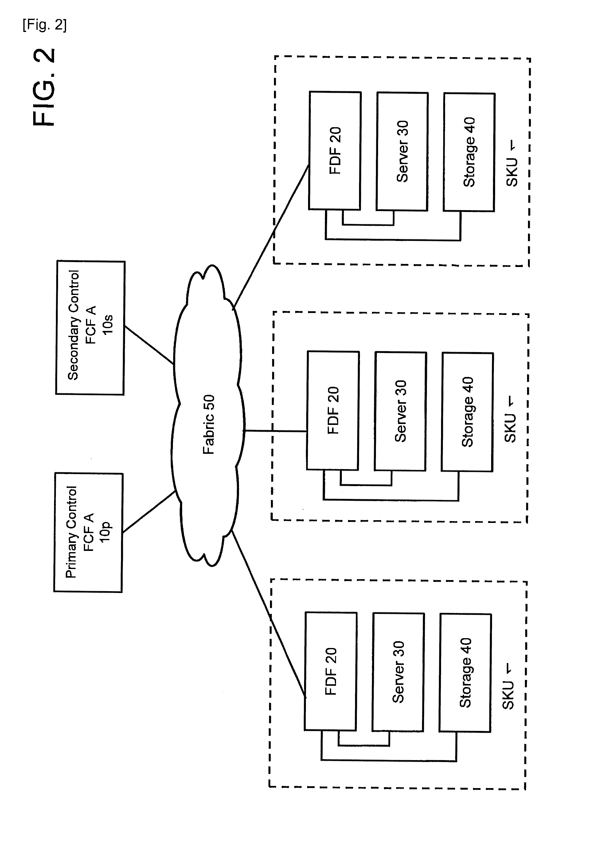
[0118]A first example will be explained by referring to FIGS. 2 through 29. FIG. 2 shows the configuration of the computer system in a case where the FCoE fabric is used.

[0119]A SKU (Stock Keeping Unit), for example, is a unit that is configured in 19-inch rack units. The SKU 1 is equipped respectively with a network apparatus 20, a server 30 (a host computer 30), and a storage apparatus 40 in accordance with customer system requirements. The SKU is the unit for shipping a tested apparatus from the factory.

[0120]The computer system of FIG. 2 comprises a fabric 50 that carries the FCoE protocol. The fabric 50, for example, is configured as an Ethernet fabric (Ethernet is a registered trademark). Two FCFs 10p and 10s, which comprise a redundant configuration, are coupled to the fabric 50.

[0121]The FCF 10p is the FCF for carrying out primary control. The FCF 10s is a secondary FCF, which is on active standby. The primary FCF 10p sends its own information to the secondary FCF 10s inform...

example 2

[0271]A second example will be explained by referring to FIGS. 32 through 38. In this example, the operation of the fabric, which has received zoning information from a storage apparatus port, will be explained. The explanation will focus on the differences with the first example.

[0272]FIG. 32 is an example of the configuration of a virtual domain 550 in a FCoE fabric.

[0273]This configuration is a specific example of the abstract network topology shown in FIG. 3.

[0274]The arrows, which couple the respective ports of FIG. 32, denote FCoE virtual links rather than physical connections. The physical connections have been omitted from the description. The physical connections are between FCF MAC (physical Ethernet ports) disposed in either the FCF or the FDF.

[0275]In FIG. 32, a total of four switches, two FCFs 10 and two FDFs 20, form virtual links with one another. A FCF MAC of the primary FCF A, a FCF MAC of the secondary FCF A, a FCF MAC of a FDF A, and a FCF MAC of a FDF B are coupl...

example 3

[0326]A third example will be explained by referring to FIGS. 39 through 42. FIG. 39 is a flowchart showing a process for collectively distributing zoning information in a case where the FDF receives login requests from multiple FCoE nodes (E-Nodes). Since this process is equivalent to a variation of the process shown in FIG. 33, the explanation will focus on the differences with FIG. 33.

[0327]S100 is the same as S60 of FIG. 33. However, in S100, a case in which a login request is simultaneously generated from another node is also taken into account. Furthermore, S101 is the same as S61 of FIG. 33.

[0328]S102 is the same as S62 of FIG. 33. However, in S102, login requests are received from each of multiple nodes.

[0329]Next, the FDF merges the zoning information received from multiple nodes, and collectively queries the FCF about the collected zoning information (S103). This query has the same content as that explained in S63 of FIG. 33.

[0330]The FDF merges the multiple pieces of zoni...


PUM


Abstract

A computer system in which one or more host computers 30 having a FC (Fibre Channel) node port and one or more storage apparatuses 40 having a FC node port are coupled via a FC fabric. The storage apparatus acquires first information related to access control for controlling access to a relevant storage apparatus by the host computer. The storage apparatus, based on the first information, creates second information for defining the host computer that is able to access the relevant storage apparatus, and registers this second information in the fabric.

Description

TECHNICAL FIELD[0001]The present invention relates to a computer system and a computer system management method.BACKGROUND ART[0002]A data center couples together large numbers of servers and multiple storage apparatuses using a Fibre Channel (FC) interface. For example, drops in apparatus performance, the end of an apparatus' service life, insufficient apparatus capacity, a dearth of network bandwidth, and system expansion will result in a data center replacing a server, network apparatus or storage apparatus with a new apparatus, adding a new apparatus, or removing an old apparatus from the computer system.[0003]With conventional server virtualization technology, multiple virtual machines can be operated in accordance with running virtualization software on a physical server. This server virtualization technology makes it possible to temporarily suspend a virtual machine that is running on one physical server and migrate this virtual machine to the virtualization software running ...

Claims


Application Information

Patent Timeline
Patent Type & Authority Applications(United States)
IPC IPC(8): G06F12/00H04L45/586
CPCG06F3/0607G06F3/0664G06F3/067H04L45/586G06F3/0647H04L49/45H04L67/1097G06F3/061H04L49/357
Inventor NAKAJIMA, AKIO
Owner HITACHI LTD
Why Eureka
Try Eureka