Pre-plumbed shower panel with clustered jets

a shower panel and clustering technology, applied in the field of showers and bath appliances, can solve the problems of difficult lower back massage for users, expensive installation of another showering fixture, and inconvenient installation of showering fixtures, so as to reduce water consumption, reduce stress and fatigue, and maximize water use

Inactive Publication Date: 2012-10-11
LIFETOUCH INNOVATIONS
View PDF5 Cites 16 Cited by
  • Summary
  • Abstract
  • Description
  • Claims
  • Application Information

AI Technical Summary

Benefits of technology

[0005]The shower panel includes six powerful tilting multi-function massage jets aligned with the critical muscle groups in the upper back, neck and shoulders of the user. The shower panel offers jet clustering that targets water pressure where it is needed most. Water jets tilt to suit every individual. Several functions allow for a deep back massage or relaxing, toning mist. The centered tilting “turbojet” adjusts to focus maximum water pressure on problem areas of the back, shoulders and neck, washing away soreness, stress and fatigue. The user can select from multiple rejuvenating massage functions for complete control over muscle health. The shower panel is designed to maximize the power of water, turning standard water pressure into high-pressure spray. An invigorating massage therapy with lower water consumption is produced using a simplified internal design, a shorter distance from water supply to jet outlets, and a succession of power increasing compression hoses. Additionally, the massage jets are designed with smaller outlet holes and more efficient internal design than prior art massage jets, yielding increased water pressure as compared to prior art massage jets.

Problems solved by technology

Unfortunately, such conventional showerheads are often limited in where they can massage the user.
For example, the position of showerhead 10 makes it difficult for the user to massage their lower back.
Moreover, installing another showering fixture is often costly and involves extensive plumbing.

Method used


Image

  • Pre-plumbed shower panel with clustered jets
  • Pre-plumbed shower panel with clustered jets
  • Pre-plumbed shower panel with clustered jets

Examples


Embodiment Construction

[0029]Reference will now be made in detail to some embodiments of the invention, examples of which are illustrated in the accompanying drawings.

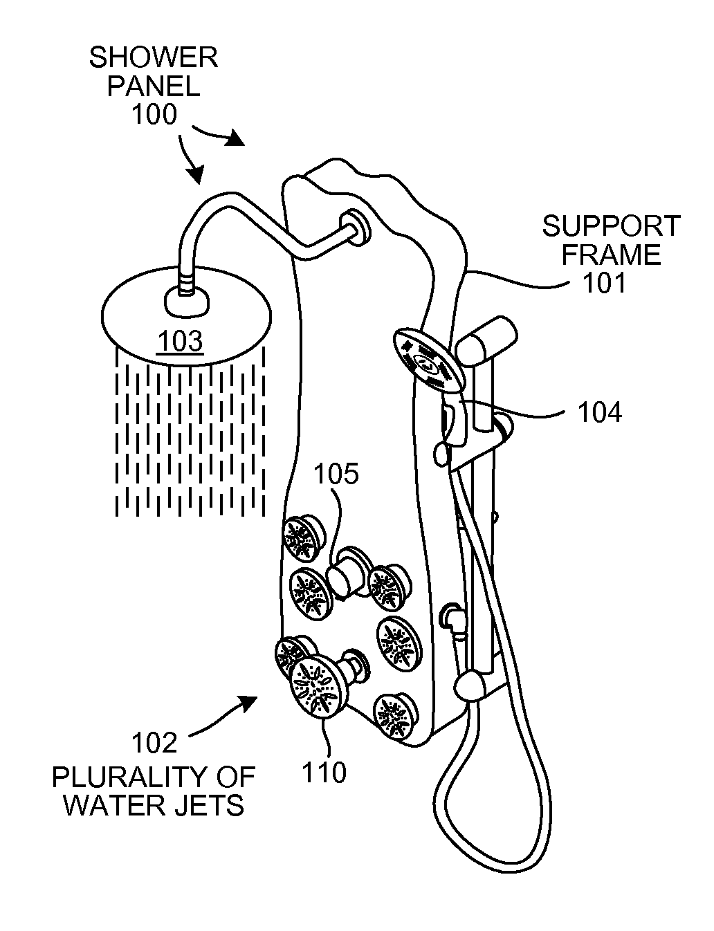
[0030]FIG. 2 is a perspective diagram of a novel shower panel 100. Shower panel 100 comprises a support frame 101, a plurality of water jets 102, an overhead shower 103, a hand nozzle 104, a control handle 105, and a side showerhead 110. Any pre-existing shower stall or pre-existing shower tub is retrofittable to support novel shower panel 100. The retrofit process involves connecting the shower panel directly to the water source and hanging shower panel 100 on mounting anchors attachable to a surface of the shower wall. Shower panel 100 utilizes the pressure balance valve and temperature control valve of the pre-existing shower without any further modification or re-plumbing behind the shower wall.

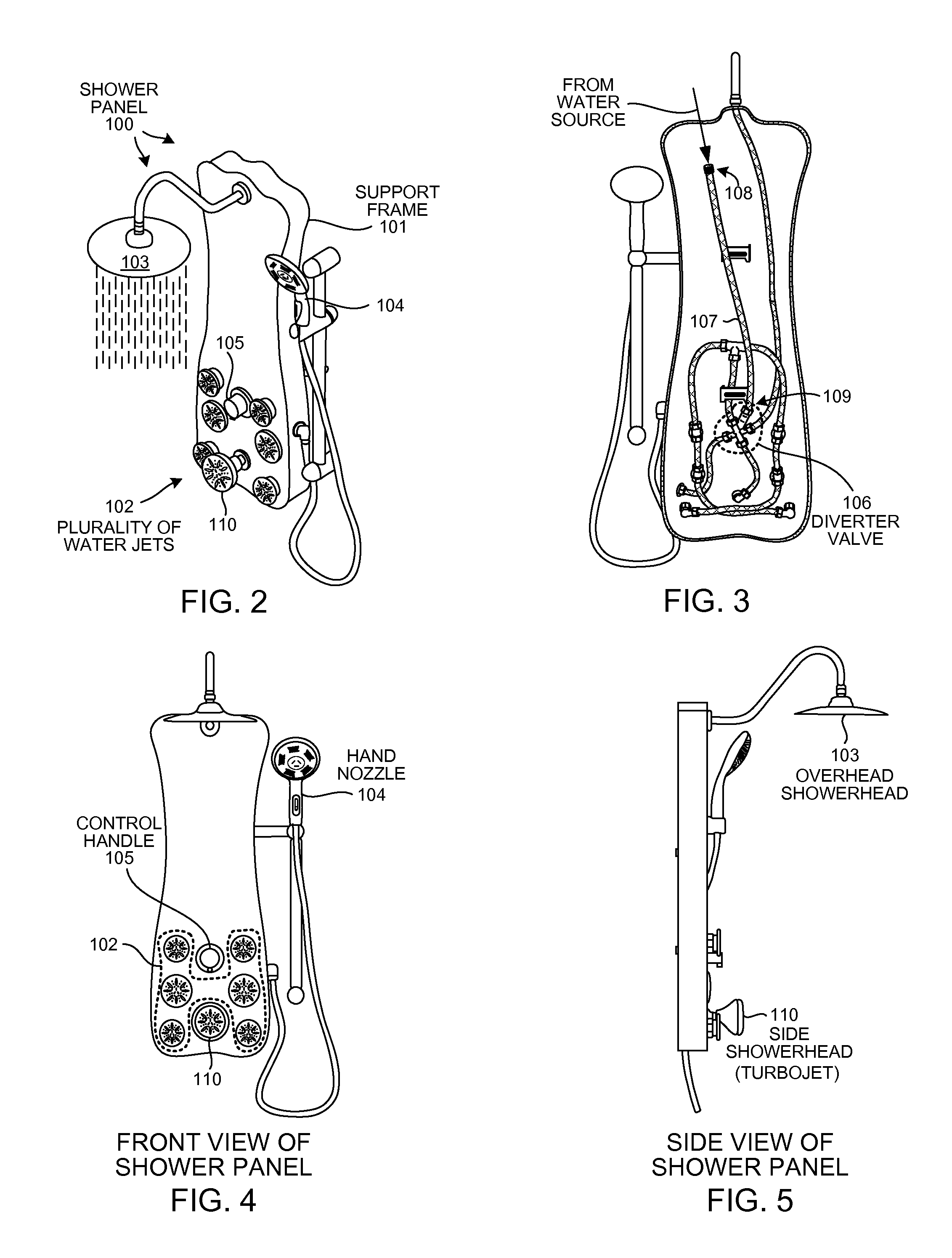
[0031]FIG. 3 is a diagram of a back view of shower panel 100 that shows the plumbing of shower panel 100. Shower panel 100 further comprises a di...


PUM

PropertyMeasurementUnit
distanceaaaaaaaaaa
adhesiveaaaaaaaaaa
diameteraaaaaaaaaa

Abstract

An existing shower is retrofitted with a novel shower panel that uses the existing on/off water pressure and temperature control valve without any re-plumbing behind the shower wall. The shower panel includes a support frame, a diverter valve, a plurality of water jets, a side showerhead, a hand nozzle and an overhead showerhead. The support frame has an open side that faces the shower wall. A first tube connects the diverter valve to the plurality of water jets. A second tube is connected to the diverter valve at a first end and has a threaded connector at the second end. The threaded connector is adapted to connect to a shower water source after the existing shower pipe is removed. The first tube has a smaller diameter than does the second tube. The plurality of water jets are arranged within a square that is twenty-five centimeters on a side.

Description

CROSS REFERENCE TO RELATED APPLICATION[0001]This application claims the benefit under 35 U.S.C. §119 of provisional application Ser. No. 61 / 473,518, entitled “Pre-Plumbed Shower Panel With Clustered Jets”, filed Apr. 8, 2011. The subject matter of provisional application Ser. No. 61 / 473,518 is incorporated herein by reference.TECHNICAL FIELD[0002]The described embodiments relate to shower and bath appliances, and specifically to an easily installed shower panel with clustered water jets that uses the existing shower valve.BACKGROUND INFORMATION[0003]FIG. 1 (Prior Art) is a perspective diagram of a conventional showerhead 10 that extends from a surface of shower wall 11. Showerhead 10 is a typical showerhead that includes a rotating bezel 12 that allows a user to adjust the spray emitted from showerhead 10. For example, by rotating bezel 12, a user can change the spray emitted from a continuous stream, to a spray that is emitted in short, concentrated bursts providing a massaging eff...

Claims


Application Information

Patent Timeline
Patent Type & Authority Applications(United States)
IPC IPC(8): A47K3/28B23P17/04
CPCA47K3/28Y10T29/49716E03C1/0408
Inventor REEVES, DONALD W.REEVES, SCOTT
Owner LIFETOUCH INNOVATIONS
Why Eureka
Try Eureka