Control lever for controlling a rotary wing, a mechanical control system including said control lever, and an aircraft

a technology for controlling a rotary wing and a control lever, which is applied in the field of flight control systems, can solve the problems of high friction in the mechanical structure and the difficulty of implementing a short cyclic stick with mechanical transmission on a rotary wing aircraft, and achieve the effect of minimizing the friction force of the set of mechanical members going from the control lever to the power member

Active Publication Date: 2012-10-11
EUROCOPTER
View PDF9 Cites 16 Cited by
  • Summary
  • Abstract
  • Description
  • Claims
  • Application Information

AI Technical Summary

Benefits of technology

[0033]The friction forces from the set of mechanical members going from the control lever to the power members are thus minimized. It thus becomes possible to use a stick with a minimized lever arm on an aircraft of considerable weight that is provided with mechanical flight controls, as opposed to electrical flight controls.

Problems solved by technology

Nevertheless, such a mechanical architecture generates high levels of friction, with these friction forces being maximized by the presence of phasing means between the cyclic control lever and the mixing unit.
It would then appear difficult to implement a short cyclic stick with mechanical transmission on a rotary wing aircraft, since the lever arm of such a stick would appear to be difficult to make compatible with such friction forces.

Method used


Image

  • Control lever for controlling a rotary wing, a mechanical control system including said control lever, and an aircraft
  • Control lever for controlling a rotary wing, a mechanical control system including said control lever, and an aircraft
  • Control lever for controlling a rotary wing, a mechanical control system including said control lever, and an aircraft

Examples


first embodiment

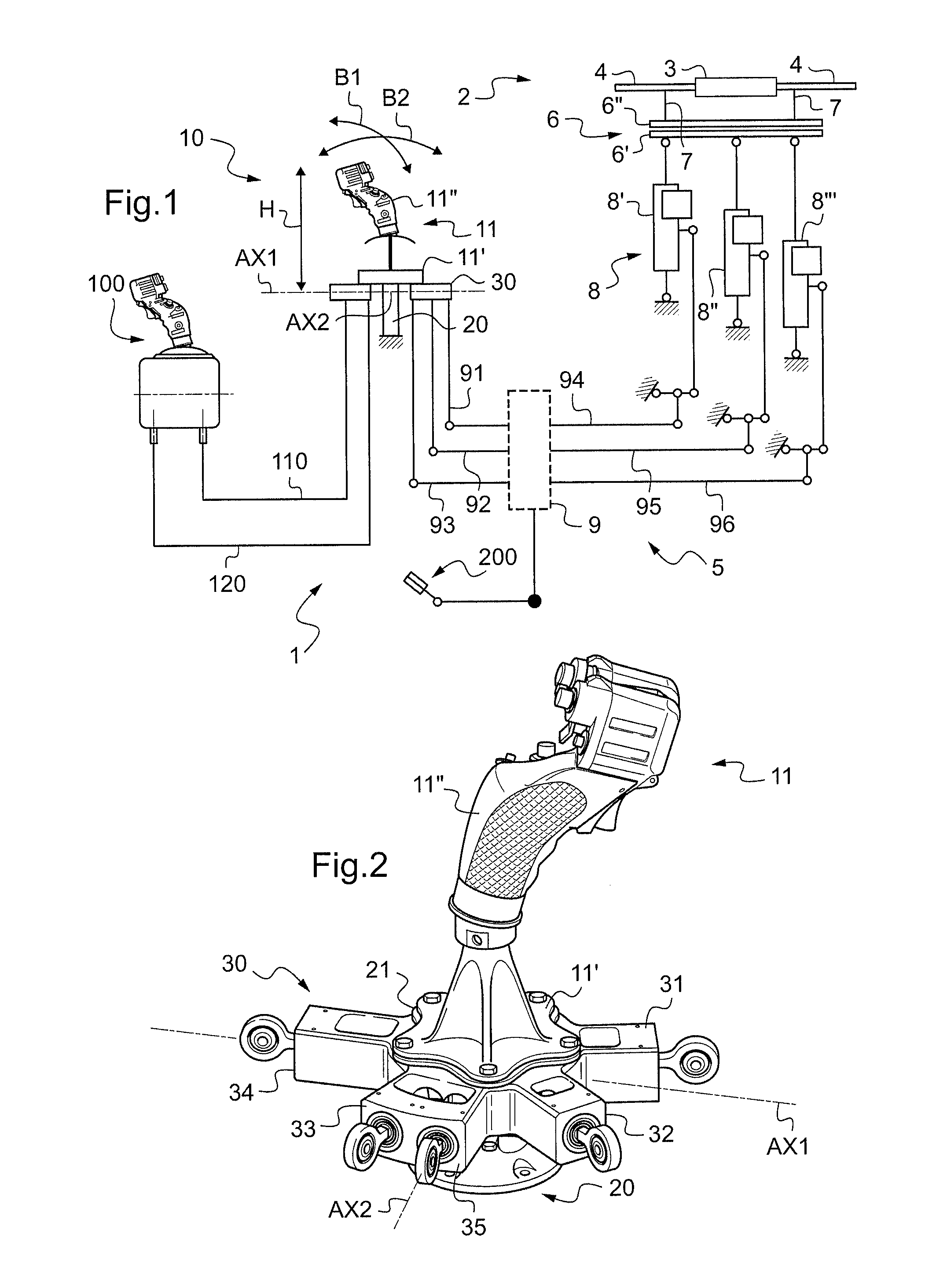
[0059]FIG. 1 shows an aircraft 1 in a first embodiment, the aircraft being shown schematically to avoid pointlessly overloading FIG. 1. The aircraft 1 has a rotary wing 2 provided with a hub 3 carrying a plurality of blades 4. Under such circumstances, the aircraft 1 has a control system 5 for controlling the cyclic pitch of the blade 4, or indeed for controlling the collective pitch of said blades 4.

[0060]The control system 5 is a mechanical system controlling the pitch of the blades 4, and it comprises a set 6 of control swashplates, the set 6 including a non-rotary swashplate 6′ that co-operates with a rotary swashplate 6″ that is in turn connected to each of the blades 4 by a respective pitch rod 7. Such a set is sometimes known under the term “cyclic swashplate”.

[0061]The control system 5 then includes a control lever 10 for cyclically controlling the pitch of the blades 4 by acting on the set 6 of control swashplates.

[0062]In order to minimize the forces needed to operate the ...

second embodiment

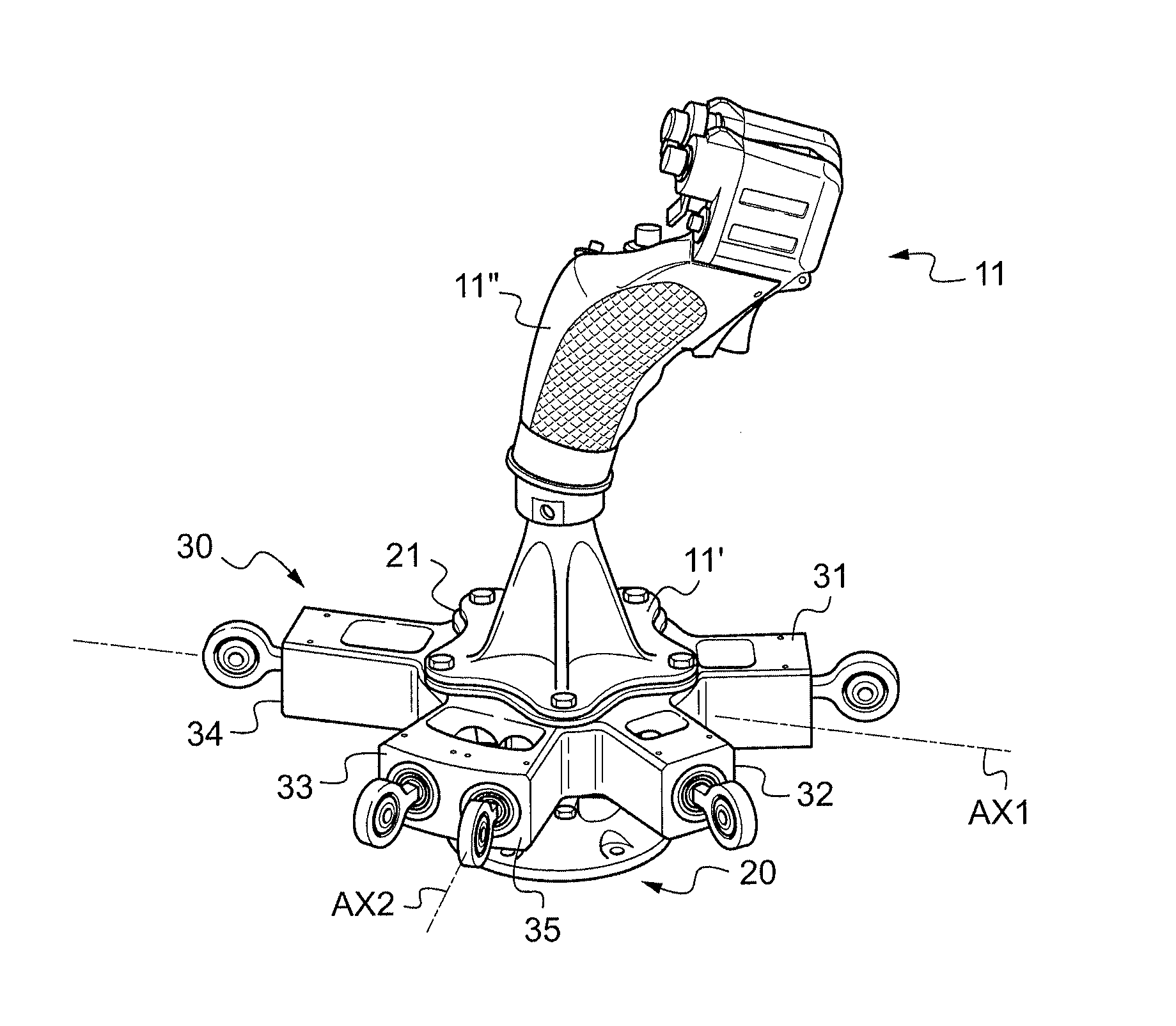
[0079]With reference to FIG. 2, in a second embodiment, the phasing means 30 are fastened to a movable portion 21 of the carrier structure 20.

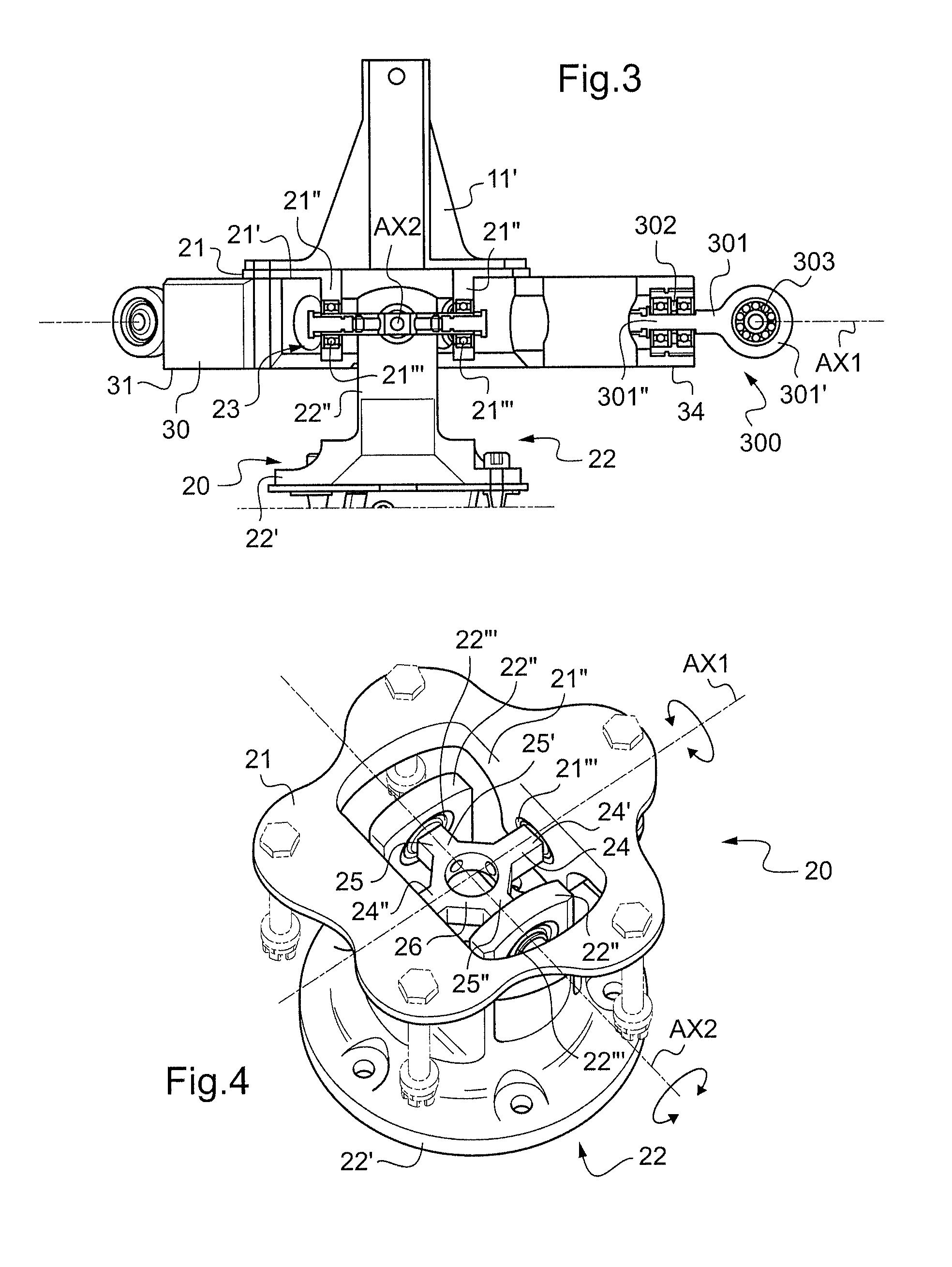
[0080]As can be seen with reference to FIG. 4, the carrier structure 20 has a movable portion 21 that is movable about the first hinge axis AX1 and about the second hinge axis AX2, and also a stationary portion 22 that is fastened to a point in the cabin of an aircraft.

[0081]The carrier structure 20 is then provided with a hinge connecting the movable portion 21 to the stationary portion 22, this hinge including link means 23 of the spider type. The link means 23 are provided with a first shaft 24 that is elongate along the first hinge axis AX1 and with a second shaft 25 that is elongate along the second hinge axis AX2.

[0082]Each shaft 24 and 25 has two distinct extreme portions 24′&24″ and 25′&25″ that are connected together by a perforated central portion 26.

[0083]Consequently, the movable portion has a first plate 21′ carrying two first che...


PUM


Abstract

A control lever (10) provided with a stick (11) extending axially from a stand (11′) towards grip means (11″) and with a carrier structure (20) for said stick (11) that is hinged about a first hinge axis (AX1) and about a second hinge axis (AX2). The control lever (10) includes phasing means (30) constrained to move in rotation with said stick (11) about said first hinge axis (AX1) and about said second hinge axis (AX2), said phasing means (30) comprising at least three main arms (31, 32, 33), each for controlling a respective power member (8′, 8″, 8″′) that is connected to a set (6) of swashplates for controlling a rotary wing (2).

Description

CROSS REFERENCE TO RELATED APPLICATIONS[0001]The present application claims priority to French patent application FR 11 / 01031 filed on Apr. 6, 2011, the disclosure of which is incorporated in its entirety by reference herein.BACKGROUND OF THE INVENTION[0002](1) Field of the Invention[0003]The present invention relates to a control lever for controlling a rotary wing, to a mechanical control system including said lever, and to an aircraft fitted with said control system.[0004]The invention lies in the field of aircraft, in particular rotorcraft, and it relates more particularly to flight control systems that are actuated by a human pilot to control a rotary wing aircraft, more particularly in pitching and in roll. More specifically, the invention relates to control levers for controlling the flight directions of an aircraft, and in particular for modifying the pitch of the blades of the rotary wing fitted to a rotorcraft. In particular, the invention provides a cyclic stick for mecha...

Claims


Application Information

Patent Timeline
Patent Type & Authority Applications(United States)
IPC IPC(8): G05G9/04
CPCB64C13/30B64C13/40Y10T74/20201B64C27/56G05G9/047B64C27/54B64C27/605
Inventor COUDERC, GÈRARDBIEST, ROMUALD
Owner EUROCOPTER
Why Eureka
Try Eureka