Suspension arrangement for a wheel suspension of a motor vehicle

a suspension arrangement and motor technology, applied in resilient suspensions, interconnection systems, vehicle components, etc., can solve the problems of insufficient type of rotary actuators for vehicle installation, reduced overall spring stiffness, and inability to prolong, so as to reduce the torsional stress of torsion-bar springs, reduce the diameter and weight, and reduce the spring rate of the suspension arrangement

Active Publication Date: 2012-10-11
AUDI AG
View PDF12 Cites 3 Cited by
  • Summary
  • Abstract
  • Description
  • Claims
  • Application Information

AI Technical Summary

Benefits of technology

[0007]In accordance with the present invention, the output lever which is connected to the torsion-bar spring is no longer rigid without spring characteristics but rather is configured as a flexible spring with defined spring rate. Thus, the torsion-bar spring is followed or superimposed in a simple manner by a flexible spring connected in series to lower the spring rate of the suspension arrangement and to reduce torsional stress of the torsion-bar spring. As a result, it is possible to use a torsion-bar spring of lesser diameter and weight.
[0008]According to another advantageous feature of the present invention, the torsion-bar spring may include a tube spring extending from the actuator towards a midsection of the motor vehicle and a solid rod in driving relationship with the tube spring. The nested torsion-bar assembly comprised of tube spring and solid rod type spring is thus expanded with the output lever as a third resilient component. As a result, the overall spring rate can be adjusted downwards while yet maintaining geometric dimensions, i.e. the length of the torsion-bar assembly. In addition, the rotary actuator can be installed even in smaller vehicles that require a reduction in the overall spring stiffness of the wheel suspension.
[0009]According to another advantageous feature of the present invention, the output lever may be configured as bending beam of same bending stress. As a result, the output lever can be made of optimum weight from spring steel with even stress distribution.
[0010]According to another advantageous feature of the present invention, the output lever may have a substantial horizontal orientation, with vertical coupling rods articulating the output lever to the wheel control element. Advantageously, the output lever has a cross section which can taper from an attachment point upon the torsion-bar spring to the coupling rods. The provision of the vertically oriented coupling rods further prevents the wheel control elements from applying torques that are generated during travel and may cause a tilting of the flexible spring.

Problems solved by technology

This type of rotary actuator is inadequate for installation in vehicles, especially smaller vehicles which require a reduction of the overall spring stiffness, because a softer torsion-bar spring would have to be accompanied by a prolongation of the solid rod and the hollow rod.
Such a prolongation is however unacceptable in view of the available tight space conditions in the area of the wheel suspension.

Method used


Image

  • Suspension arrangement for a wheel suspension of a motor vehicle
  • Suspension arrangement for a wheel suspension of a motor vehicle
  • Suspension arrangement for a wheel suspension of a motor vehicle

Examples


Embodiment Construction

[0018]Throughout all the figures, same or corresponding elements may generally be indicated by same reference numerals. These depicted embodiments are to be understood as illustrative of the invention and not as limiting in any way. It should also be understood that the figures are not necessarily to scale and that the embodiments are sometimes illustrated by graphic symbols, phantom lines, diagrammatic representations and fragmentary views. In certain instances, details which are not necessary for an understanding of the present invention or which render other details difficult to perceive may have been omitted.

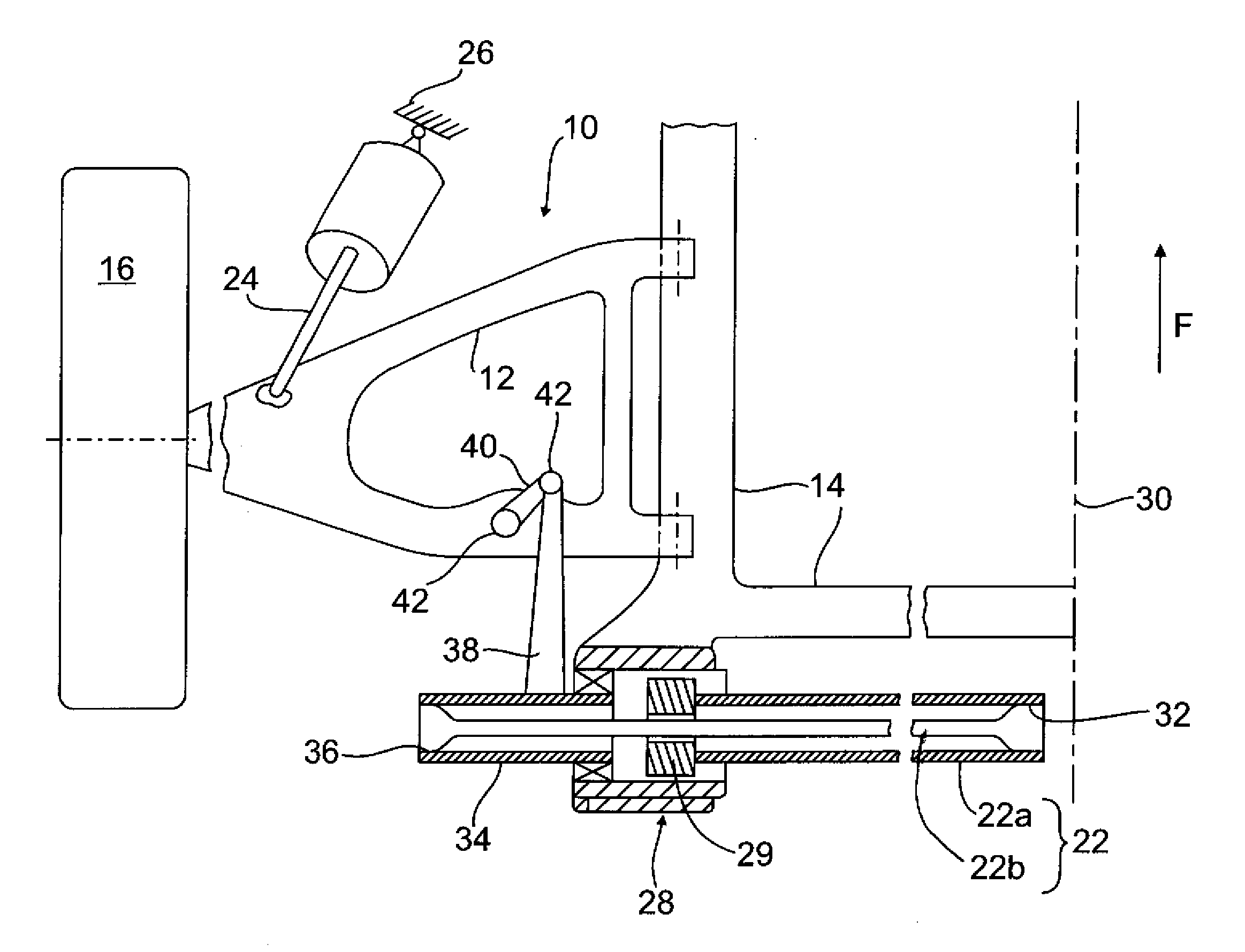
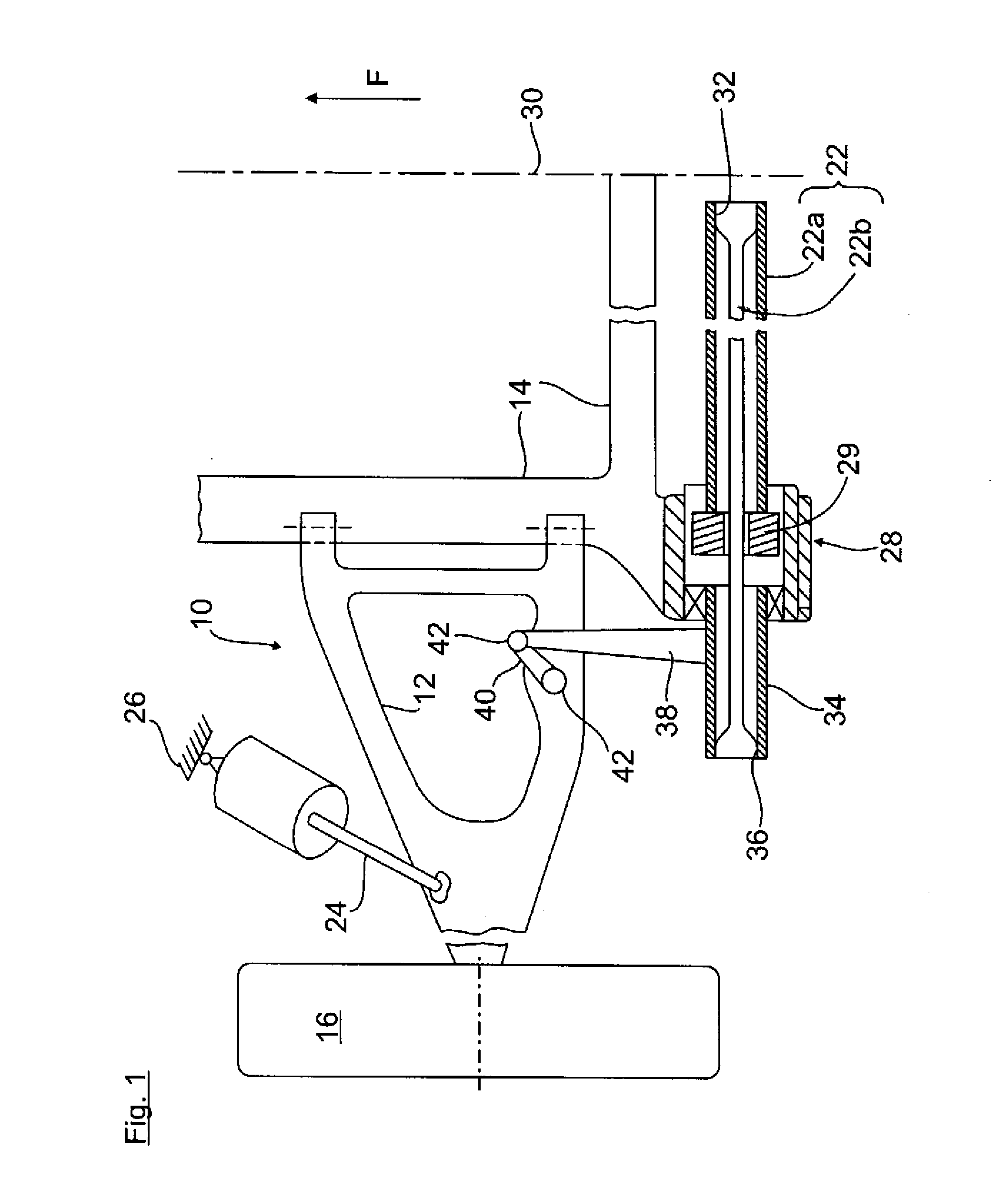
[0019]Turning now to the drawing, and in particular to FIG. 1, there is shown a plan view of a lower plane of a left-hand wheel suspension of a rear axle of a motor vehicle, generally designated by reference numeral 10 and including a lower control arm 12 having one end hinged to a subframe 14, shown only in part, and another end hinged to a wheel carrier (not shown) for a r...


PUM


Abstract

A suspension arrangement for a wheel suspension of a motor vehicle includes an output lever hinged directly or indirectly to a wheel control element and configured as a flexible spring of defined spring rate. A transverse torsion-bar spring acts on the output lever, with an actuator adjusting a pretension of the torsion-bar spring.

Description

CROSS-REFERENCES TO RELATED APPLICATIONS[0001]This application claims the priority of German Patent Application, Serial No. 10 2011 016 540.1, filed Apr. 8, 2011, pursuant to 35 U.S.C. 119(a)-(d), the content of which is incorporated herein by reference in its entirety as if fully set forth herein.BACKGROUND OF THE INVENTION[0002]The present invention relates to a suspension arrangement for a wheel suspension of a motor.[0003]The following discussion of related art is provided to assist the reader in understanding the advantages of the invention, and is not to be construed as an admission that this related art is prior art to this invention.[0004]DE 10 2009 005 899 A1 describes a stabilizer for installation on a wheel suspension. The stabilizer has a torsion-bar spring which can be actuated by an actuator. The torsion-bar spring is constructed of a solid rod and a radially outer, tubular hollow rod, both made of spring steel and connected by a spline. A support spring as primary spr...

Claims


Application Information

Patent Timeline
Patent Type & Authority Applications(United States)
IPC IPC(8): B60G3/04
CPCB60G11/44B60G17/025B60G2206/15B60G2204/1224B60G2206/11B60G21/0555
Inventor MICHEL, WILFRIED
Owner AUDI AG
Why Eureka
Try Eureka