Touch surface with identification of reduced performance

a technology of touch surface and performance reduction, applied in the field of touch-sensitive panels, can solve the problems of difficult application of techniques, difficult to distinguish a signal decrease, and loss of ability to accurately identify touches on the panel, and achieve the effect of reducing performance, efficiently processing, and efficiently determining the location

Inactive Publication Date: 2012-10-11
FLATFROG LAB
View PDF6 Cites 76 Cited by
  • Summary
  • Abstract
  • Description
  • Claims
  • Application Information

AI Technical Summary

Benefits of technology

[0036]The determining of the location may be performed independently of the identifying of a reduced performance, even though it is possible to take the reduced performance into account when determining the location. In any case, the device may be capable of determining touch locations while simultaneously detecting degradation or failure of components of the apparatus, which may be advantageous in that a possibility to handle any effects of the degradation is provided.
[0037]As noted above, the device may be particularly suitable for use with an FTIR system, since the relatively complex signals that reflect the attenuation may be efficiently processed. In particular, the device has been found surprisingly promising in respect of efficiently determining the location while still employing comparatively simple and efficient data processing for identifying performance degradations.

Problems solved by technology

However, in case some components such as light emitters and light detectors degrade or fail, the panels would exhibit a gradual or even total loss of capability of accurately identifying touches.
This technique may be difficult to apply in an FTIR system, where the light is not blocked by the object but merely attenuated, e.g. in the range of 0.1-10% depending on the type of object and also on the motion pattern of the object on the touch surface.
In an FTIR system, it may therefore be difficult to distinguish a signal decrease caused by a touch from a signal decrease caused by a degraded or defect component.
Typically, the signal reflects not only energy of light received by the light detection arrangement, but also noise that for some reason may be caused by a component of the apparatus.
The reduced performance may comprise a gradual lowering of light output from the illumination arrangement or a gradually decreased capability of detecting light by the light detection arrangement, and may comprise an increased noise level caused by any of the illumination arrangement and light detection arrangement.
The reduced performance may also comprise complete breakdown of any of the illumination arrangement and the light detection arrangement or breakdown of only a part thereof, such as breakdown of a certain light emitter or light detector.
However, the current parameter value must not necessarily be obtained at the current real time.
The noise characteristic may comprise the level of thermal noise or shot noise, which is often inherent to the apparatus but which tend to increase when a component performs less well.
The noise level may comprise other types of noise that often is affected by defects in components of the apparatus, such as flicker noise and burst noise, as well as ambient electromagnetic interference.

Method used


Image

  • Touch surface with identification of reduced performance
  • Touch surface with identification of reduced performance
  • Touch surface with identification of reduced performance

Examples


Embodiment Construction

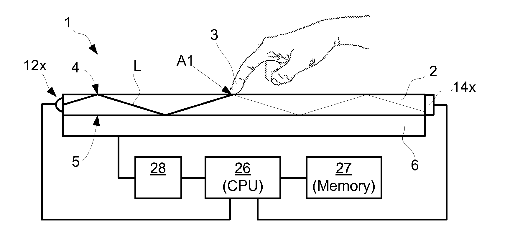
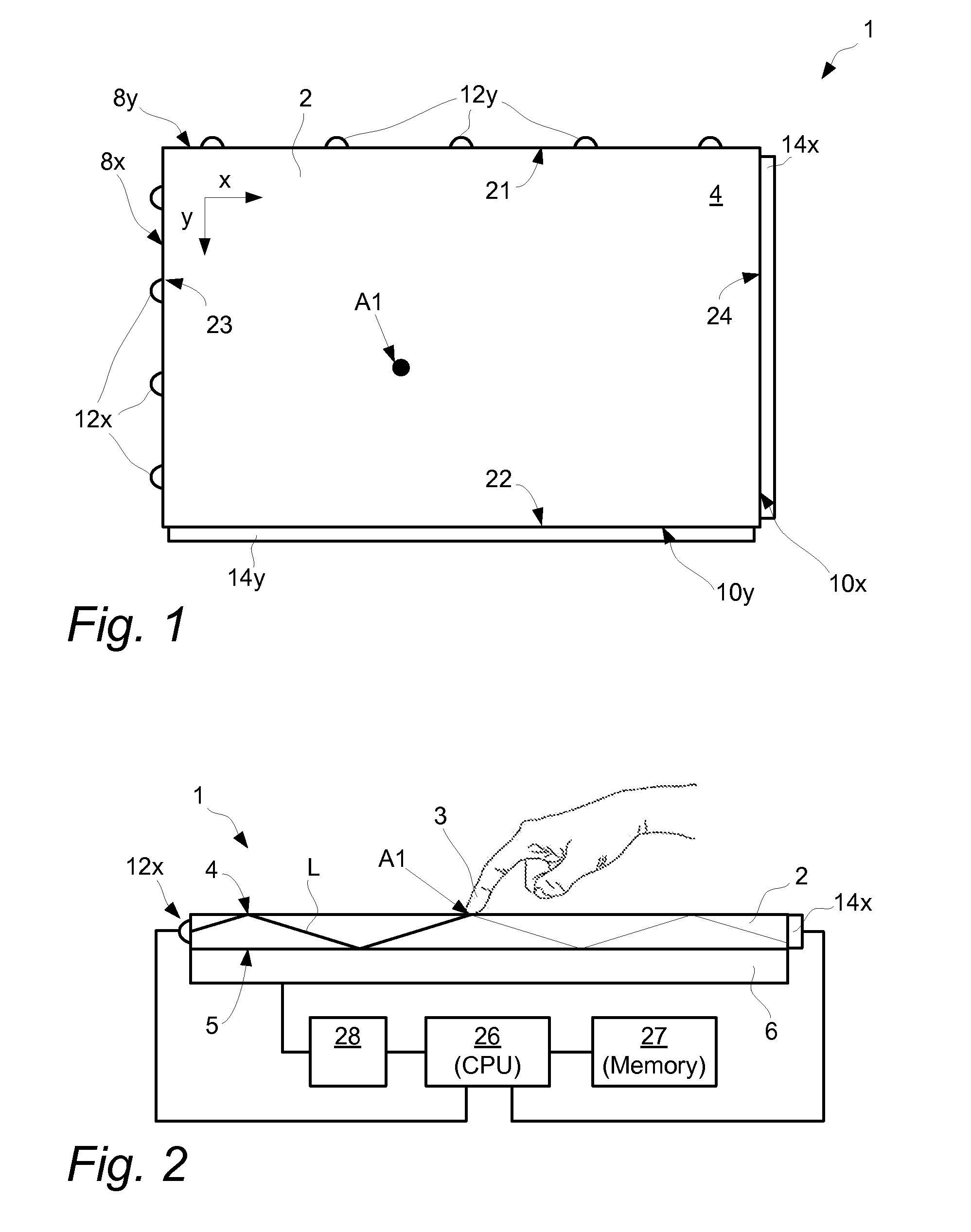
[0067]FIGS. 1 and 2 illustrate an embodiment of touch-sensing apparatus 1 for determining a location A1 of an object 3 that touches a touch surface 4. The touch-sensing apparatus 1 includes a light transmissive panel 2 that may be planar or curved. The panel 2 defines the touch surface 4 and an opposite surface 5 opposite and generally parallel with the touch surface 4. The panel 2 is configured to allow light L to propagate inside the panel 2 by internal reflection between the touch surface 4 and the opposite surface 5.

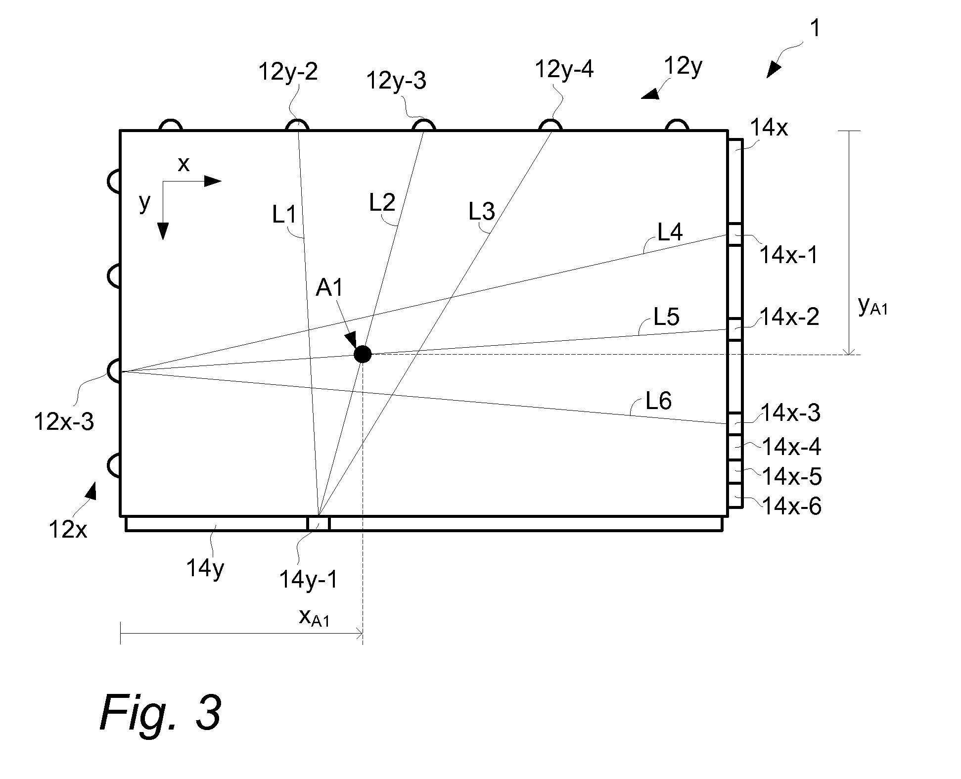
[0068]In FIG. 1, a Cartesian coordinate system has been introduced, with the x-axis being parallel to a first side 21 and to a second side 22 of the panel 2 while the y-axis is parallel to a third side 23 and to a fourth side 24 of the panel 2. The exemplified panel 2 has a rectangular shape but may just as well be e.g. circular, elliptical, triangular or polygonal, and another coordinate system such as a polar, elliptic or parabolic coordinate system may be used for...


PUM


Abstract

A device is configured to process data from a touch-sensitive apparatus for the purpose of identifying a reduced performance of components in the apparatus. The apparatus may be an FTIR system that comprises a light transmissive panel, an illumination arrangement for introducing light into the panel, and a light detection arrangement for receiving the light propagating in the panel and for measuring the energy of the received light. The device comprises a processor unit which is configured to obtain a signal comprising a time series of signal values that represent the energy of the light received by the light detection arrangement; calculate a parameter value representing a temporal variability of the signal values in the signal; and identify, based on the parameter value, a reduced performance of any of the illumination arrangement and the light detection arrangement. The temporal variability may be calculated to represent one of an absolute noise level and a signal-to-noise ratio of the signal, and enables the reduced performance to be identified while objects touch the light transmissive panel.

Description

CROSS-REFERENCE TO RELATED APPLICATIONS[0001]The present application claims the benefit of Swedish patent application No. 0950997-7, filed on 21 Dec. 2009, and U.S. provisional application No. 61 / 288,416, filed on 21 Dec. 2009, both of which are incorporated herein by reference.TECHNICAL FIELD[0002]The invention relates to touch-sensitive panels and data processing techniques in relation to such panels.BACKGROUND ART[0003]To an increasing extent, touch-sensitive panels are being used for providing input data to computers, cell phones, electronic measurement and test equipment, gaming devices, etc. The panel may be provided with a graphical user interface (GUI) for a user to interact with using e.g. a pointer, stylus or one or more fingers. The GUI may be fixed or dynamic. A fixed GUI may e.g. be in the form of printed matter placed over, under or inside the panel. A dynamic GUI may be provided by a display screen integrated with, or placed underneath, the panel or by an image being ...

Claims


Application Information

Patent Timeline
Patent Type & Authority Applications(United States)
IPC IPC(8): G06F3/042
CPCG06F3/0418G06F2203/04109G06F3/0428
Inventor CHRISTIANSSON, TOMASFAHRAEUS, CHRISTERWASSVIK, OLA
Owner FLATFROG LAB
Why Eureka
Try Eureka