Pmr write head with assisted magnetic layer

a write head and magnetic layer technology, applied in the field of thin magnetic film, can solve the problems of reducing the writability (magnetic field) of the writer on the magnetic recording media, limiting the achievement of a higher recording area density, and the current technology cannot enable further field gradient improvement. , to achieve the effect of improving field amplitude and field gradient, increasing bpi

Active Publication Date: 2012-10-11
HEADWAY TECH INC
View PDF4 Cites 7 Cited by
  • Summary
  • Abstract
  • Description
  • Claims
  • Application Information

AI Technical Summary

Benefits of technology

[0012]One objective of the present invention is to provide additional magnetic charge at the trailing edge of the recording field to improve field amplitude and field gradient at the ABS and thereby increase BPI as required for high area density PMR writers.
[0014]According to the embodiments of the present invention, the first objective is achieved with a magnetic assist layer formed on a trailing side of a main pole and adjoining a write gap layer. The magnetic assist layer has a width in a cross-track direction that is essentially equal to that of the main pole track width, a thickness in a down track direction of 5 to 20 nm, and extends a distance of 100 to 500 nm from the ABS toward a back end of the PMR writer. Preferably, the magnetic assist layer is comprised of an anisotropic magnetic material. In one embodiment, the magnetic assist layer (MAL) has a negative crystalline anisotropy energy constant (−Ku) at room temperature. Alternatively, the magnetic assist layer has a positive crystalline anisotropy constant (+Ku). A magnetic assist layer with a (−Ku) energy constant may be deposited on a seed layer such as Ru that aligns the c-axis (hard axis) of the hexagonal crystalline MAL structure toward the main pole. The c-axis (hard axis) is preferably aligned toward the main pole for a MAL with (−Ku) energy constant while the c-axis is preferably vertical to the ABS for a MAL with a (+Ku) energy constant. Thus, magnetization of the magnetic assist layer can only be induced in a direction toward the main pole with a strong magnetic field. Furthermore, the magnetic assist layer is totally soft in a 2D plane orthogonal to the hard axis which means the magnetization of the MAL can be easily induced in any direction orthogonal to the hard axis with a weak magnetic field. As a result, magnetic charges are minimized on the trailing side of the MAL facing the trailing shield such that flux loss from the main pole to the trailing shield is insignificant thereby increasing field amplitude and field gradient at the ABS

Problems solved by technology

Therefore, narrowing the gap between a shield and main pole will only lead to an unwanted flux path from the main pole to the shield which in turn reduces the writability (magnetic field) of the writer on magnetic recording media.
This dilemma is considered one of the most significant challenges to improving current writer designs and performance.
With the constraint of write field amplitude on the magnetic medium 10, further reduction of the gap between main pole and shields is not productive which limits achieving a higher recording area density.
However, current technology does not enable further field gradient improvement when the write gap shrinks below 20 nm.
However, the stacked layers are recessed from the ABS and are not expected to entirely prevent flux leakage from the main pole to an adjacent trailing shield.

Method used


Image

  • Pmr write head with assisted magnetic layer
  • Pmr write head with assisted magnetic layer
  • Pmr write head with assisted magnetic layer

Examples


Embodiment Construction

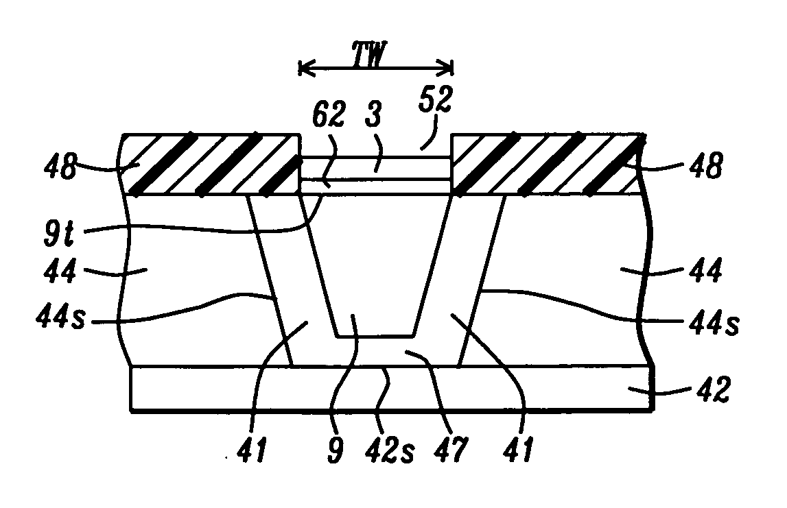
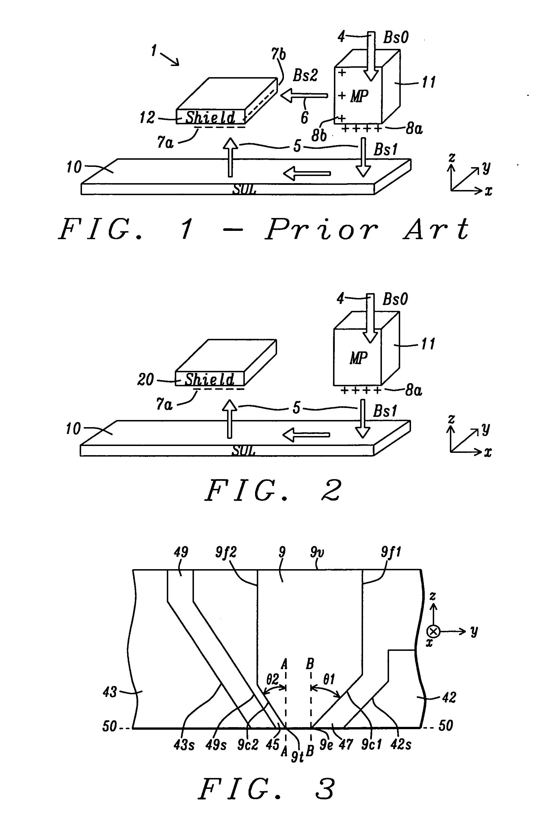
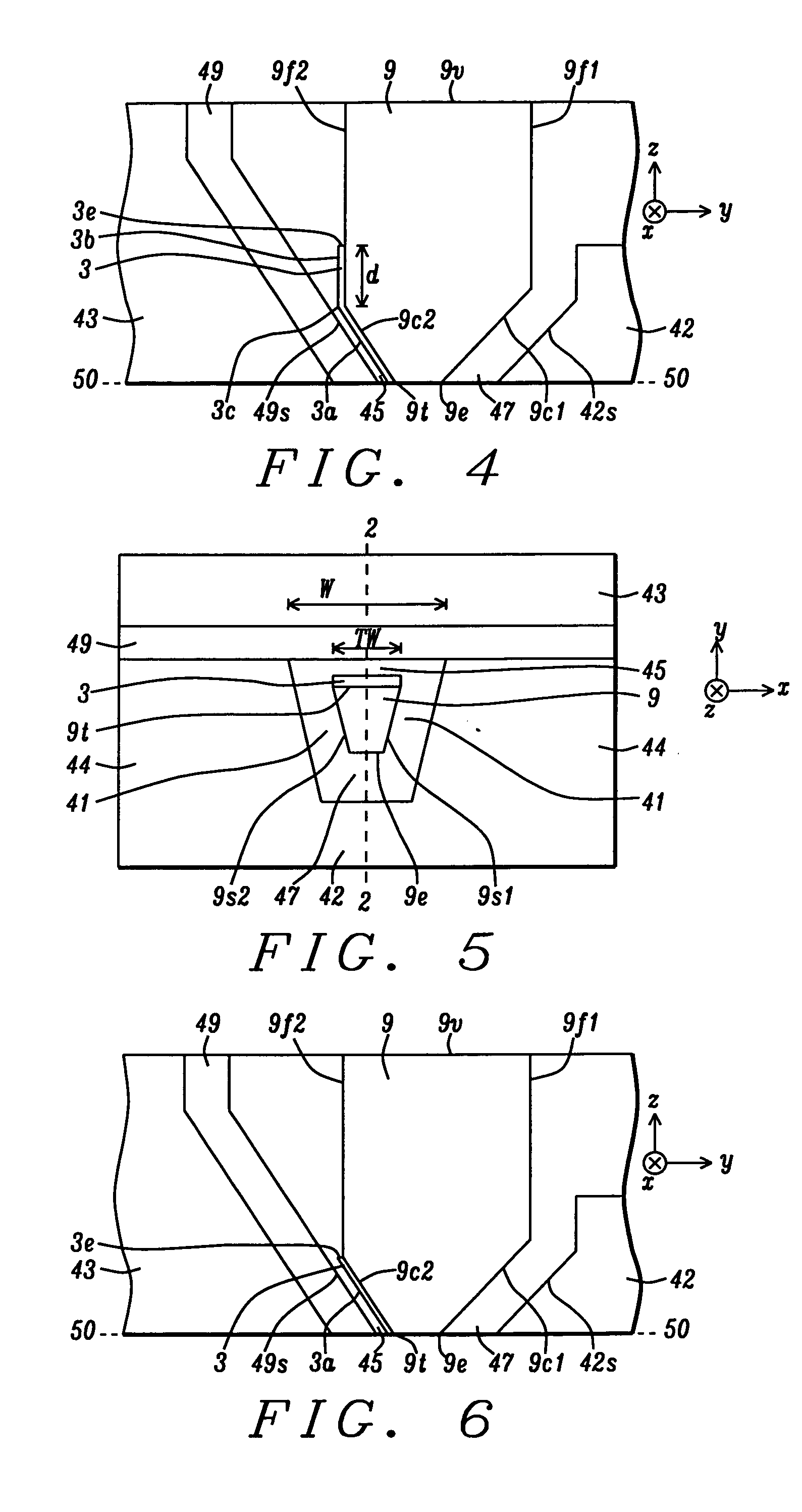
[0026]The present invention is a PMR writer design which takes advantage of the discovery that an anisotropic magnetic material may be used as a magnetic assist layer on a main pole trailing side to minimize flux loss from the main pole to a trailing shield and thereby maximize the flux field and field gradient at the main pole interface with the ABS. Although the exemplary embodiment depicts a trapezoidal shaped main pole at the ABS, the present invention also encompasses other main pole shapes. Furthermore, the main pole may have one or both of a tapered trailing edge and a tapered leading edge. Width in the context of shield structures and layers defined herein refers to a distance in a cross-track direction, and thickness or depth relates to a distance in a down-track direction. The gap layer as illustrated herein may not have a uniform thickness and the write gap portion between the main pole and trailing shield is typically thinner than the lead gap.

[0027]Referring to FIG. 2, ...


PUM

PropertyMeasurementUnit
thicknessaaaaaaaaaa
thicknessaaaaaaaaaa
distanceaaaaaaaaaa

Abstract

A PMR writer is disclosed wherein a magnetic assist layer (MAL) made of an anisotropic (−Ku) or (+Ku) magnetic material is formed along a main pole trailing side to optimize the vertical magnetic field and field gradient at the air bearing surface. A Ru seed layer is formed between the main pole and (−Ku) MAL to induce a hard axis direction toward the main pole. A (−Ku) MAL is preferably comprised of hcp-CoIr while CoPt and FePt are examples of a (+Ku) MAL. The MAL has a down-track thickness from 5 to 20 nm, a width equal to the track width in a cross-track direction, and extends 100 to 500 nm in a direction toward a back end of the main pole. As a result, flux leakage from the main pole to trailing shield is reduced and aerial density is increased. A method for fabricating the PMR writer is provided.

Description

RELATED PATENT APPLICATION[0001]This application is related to the following: Docket # HT10-031, Ser. No. ______; filing date ______; assigned to a common assignee, and herein incorporated by reference in its entirety.FIELD OF THE INVENTION[0002]The invention relates to a thin magnetic film with an anisotropic magnetic property that is added to the trailing side of a main pole and thereby provides additional magnetic charge on the ABS surface to improve writability and field gradient.BACKGROUND OF THE INVENTION[0003]In today's perpendicular magnetic recording (PMR) technology, an all wrapped around (AWA) shield writer is widely used by the major hard disk drive (HDD) manufacturers. The function of a trailing shield in an AWA structure is to improve the magnetic field gradient along a down track direction which is a key requirement for high bits per inch (BPI). Meanwhile, side shields and a leading shield serve to define a narrower writer bubble which is important for realizing highe...

Claims


Application Information

Patent Timeline
Patent Type & Authority Applications(United States)
IPC IPC(8): G11B5/31G11B5/127
CPCG11B5/1278G11B5/3116Y10T29/49032G11B5/315G11B5/3163G11B5/3146
Inventor TANG, YUHUIGUAN, LIJIEMIN, TAISONG, SUPING
Owner HEADWAY TECH INC
Why Eureka
Try Eureka