

Static Eliminator And Static Elimination Control Method
a technology of static elimination and eliminator, which is applied in the direction of electrostatic charge, emergency protective arrangement details, corona discharge, etc., can solve the problems of significant deterioration of the ion balance in the vicinity of the static eliminator, negative polarity and positive polarity of the current flowing through the discharge electrode due to corona discharge, etc., to suppress the deterioration improve the distance characteristics of the ion balance, and suppress the deteriorati
- Summary
- Abstract
- Description
- Claims
- Application Information
AI Technical Summary
Benefits of technology
Problems solved by technology
Method used
Image

Examples
first embodiment
1>
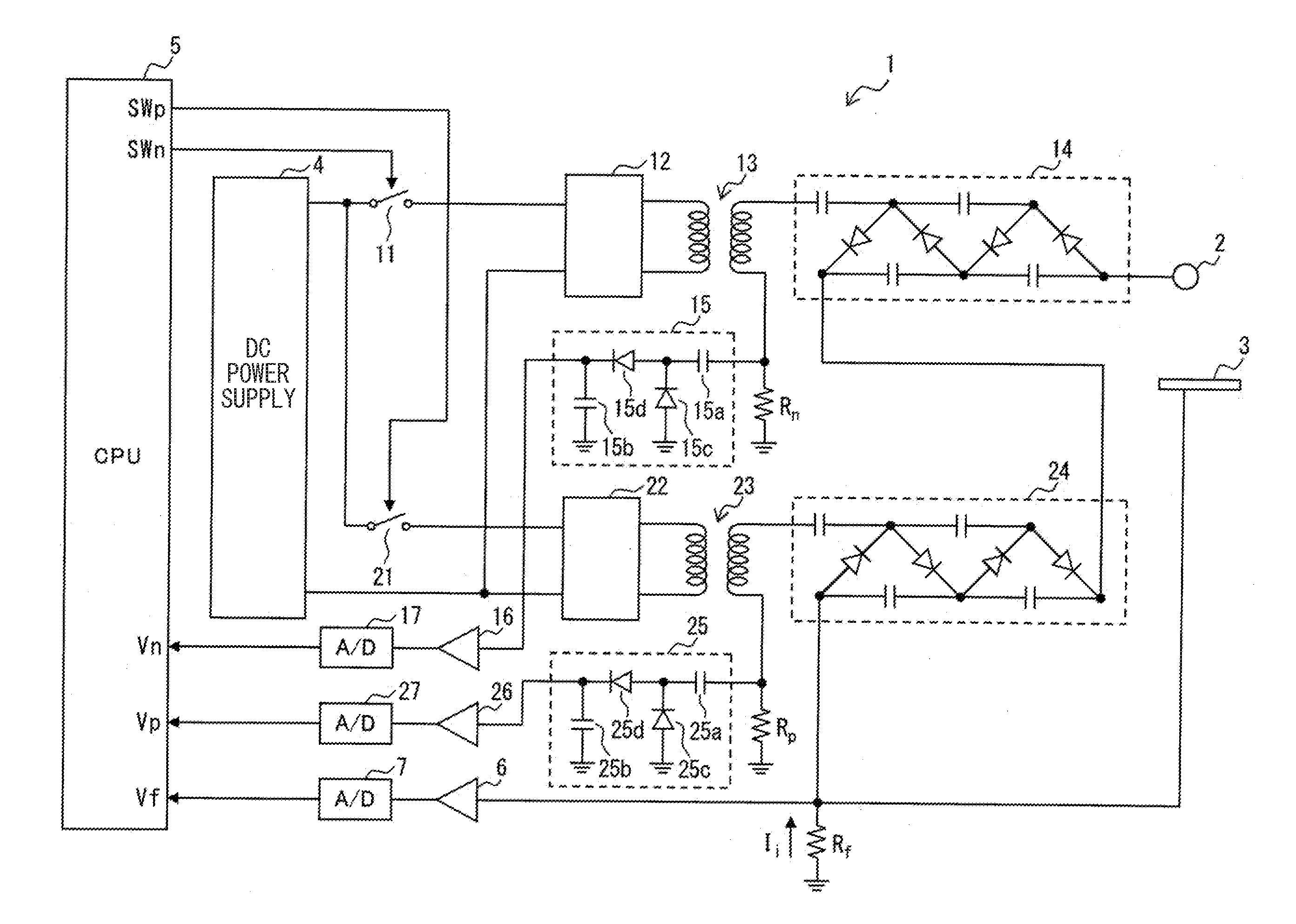
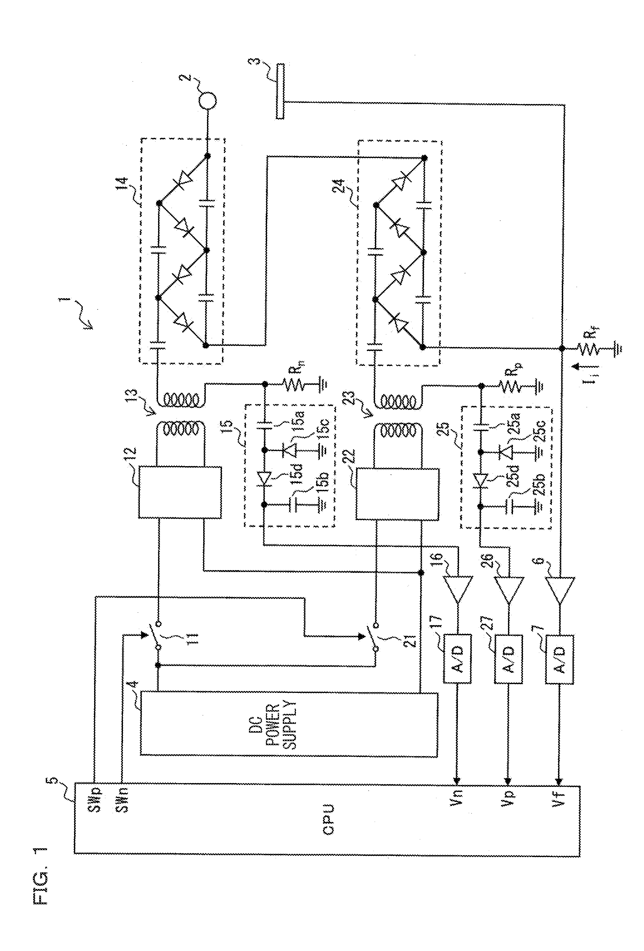
[0039]FIG. 1 is a block diagram showing a configuration example of a static eliminator 1 according to a first embodiment of the present invention, showing a pulse AC-system static eliminator. The static eliminator 1 includes a discharge electrode 2, a ground electrode 3, a DC power supply 4, a CPU 5, amplifiers 6, 16, 26, A / D converters 7, 17, 27, switching elements 11, 21, oscillator circuits 12, 22, step-up transformers 13, 23, voltage-doubler rectifier circuits 14, 24, and voltage detecting rectifier circuits 15, 25.
[0040]The oscillator circuit 12, the step-up transformer 13, and the voltage-doubler rectifier circuit 14 are an electrode driving unit for repeatedly applying a negative-side drive voltage V2 to the discharge electrode 2. The oscillator circuit 22, the step-up transformer 23, and the voltage-doubler rectifier circuit 24 are an electrode driving unit for repeatedly applying a positive-side drive voltage V1 to the discharge electrode 2.
[0041]The discharge electrode 2...
second embodiment
[0095]In the first embodiment, the example of the case has been described where the present invention is applied to the pulse AC-system static eliminator. As opposed to this, in the present embodiment, a case will be described where the present invention is applied to the AC-system static eliminator and a ratio between an application time of the positive drive voltage and an application time of the negative drive voltage will be adjusted such that the average potential V0 of the discharge electrode is held constant.
[0096]FIG. 10 is a block diagram showing a configuration example of a static eliminator 100 according to a second embodiment of the present invention. The static eliminator 100 is an AC-system static eliminator in which an AC voltage is applied to a single discharge electrode 104, and is made up of an AC power supply 101, a voltage waveform adjuster circuit 102, a step-up transformer 103, and a DC biasing DC power supply 105. Herein, a control section that controls the vo...
third embodiment
[0104]In the first embodiment, the example of the case has been described where the present invention is applied to the pulse AC-system static eliminator. As opposed to this, in the present embodiment, a case will be described where the present invention is applied to the pulse DC-system static eliminator and a ratio between an application time of the positive-side drive voltage and an application time of the negative-side drive voltage will be adjusted such that the average potential V0 is held constant.
[0105]FIG. 12 is a block diagram showing a configuration example of a static eliminator 200 according to a third embodiment of the present invention. The static eliminator 100 is a pulse DC-system static eliminator in which a pulse-like drive voltage is alternately applied to a positive-side electrode 205 and a negative-side electrode 215, and the static eliminator 100 includes DC power supplies 201, 211, oscillator circuits 202, 212, step-up transformers 203, 213, and voltage-doubl...
PUM
 Abstract
Description
Claims
Application Information