
Non-Destructive Analysis of an Object

a non-destructive analysis and object technology, applied in material analysis using wave/particle radiation, instruments, nuclear engineering, etc., can solve the problems of low quality images and two-dimensional ct slices

Inactive Publication Date: 2012-10-11
ILLINOIS TOOL WORKS INC
View PDF1 Cites 18 Cited by
  • Summary
  • Abstract
  • Description
  • Claims
  • Application Information

AI Technical Summary

Benefits of technology

[0005]Another aspect is a CT scanning system for non-destructive analysis of an object. The system includes a radiation source arranged to radiate the object and a detector arranged to measure radiation that has passed through the object. In addition, the system comprises a stage upon which the object is placed. The stage is configured to rotate the object in a continuous or step-by-step manner. The stage is located between the radiation source and the detector. The

Problems solved by technology

A few years ago, a complete industrial cone-beam CT scan would take hours or even days and most of the time only provides results in two-dimensional CT slices and low quality images.

Method used


Image

  • Non-Destructive Analysis of an Object
  • Non-Destructive Analysis of an Object
  • Non-Destructive Analysis of an Object

Examples


Embodiment Construction

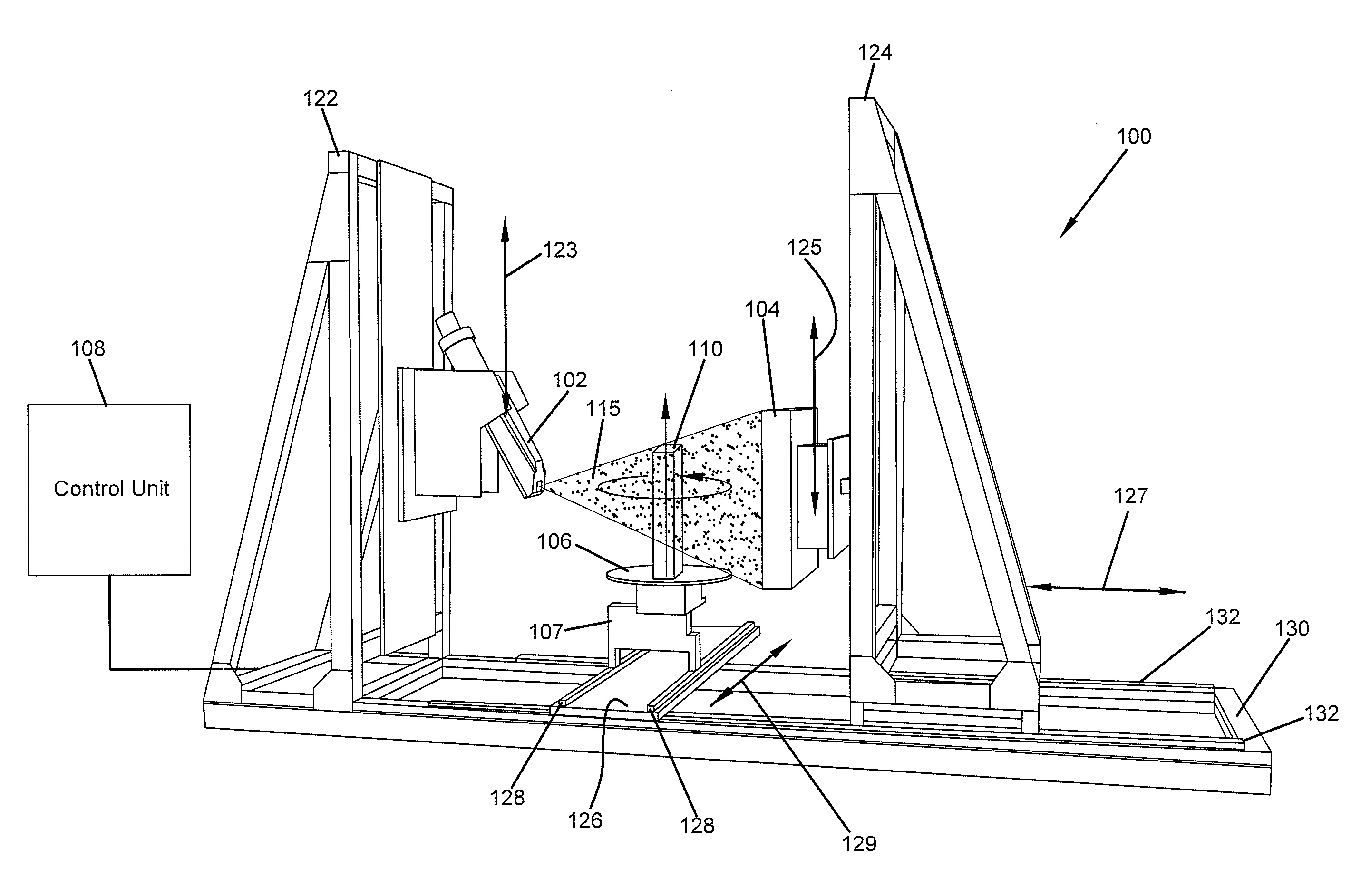
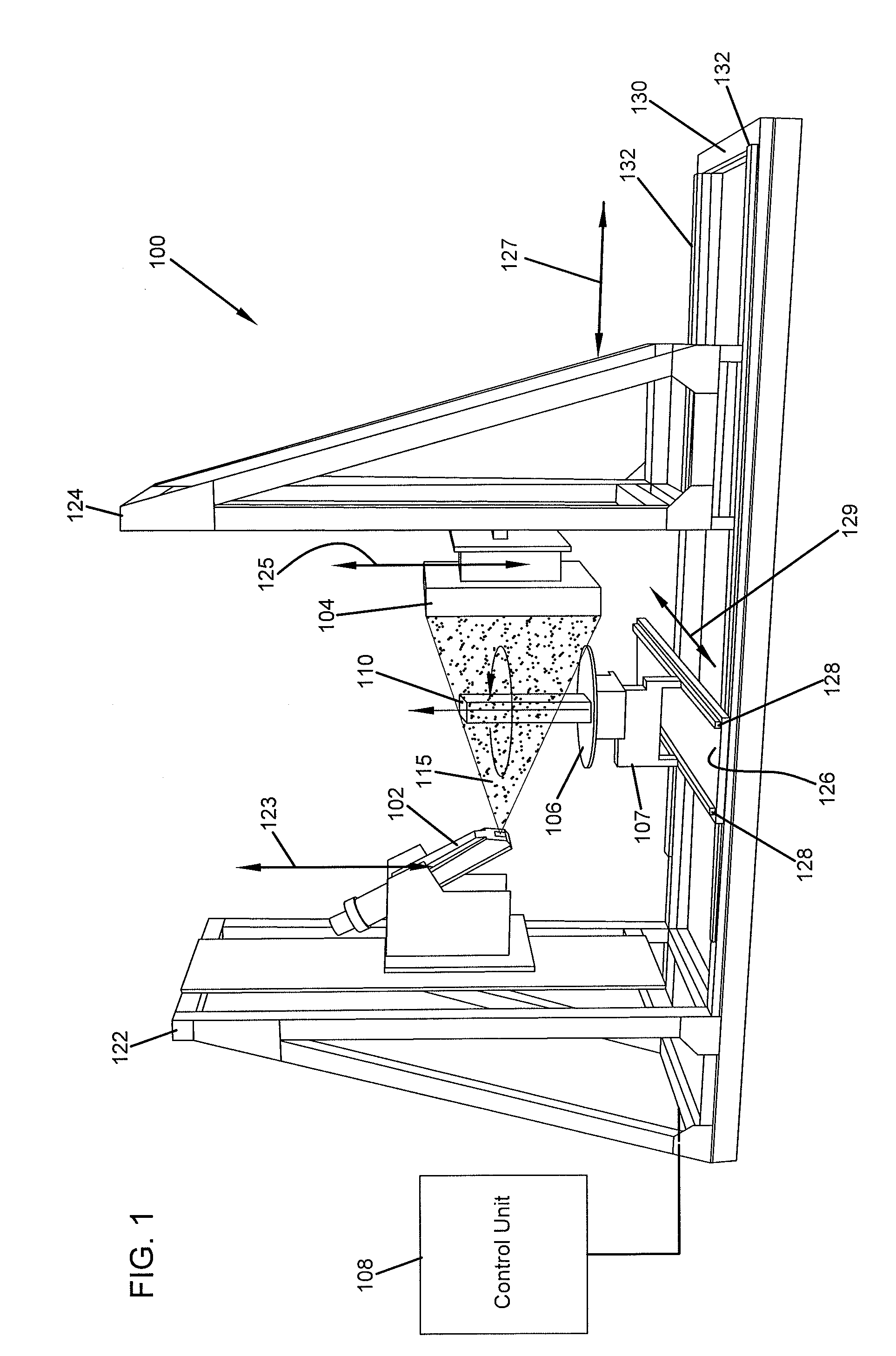
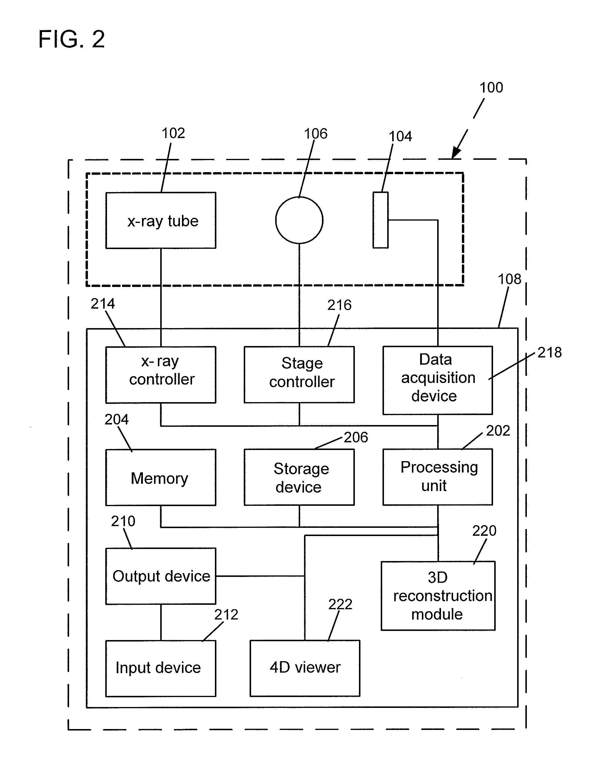
[0021]FIG. 1 is a schematic view of an exemplary computed tomography (CT) scanning system 100. The CT scanning system 100 generates four-dimensional (4D) representations of objects. To generate a 4D representation of an object 110, the CT scanning system 100 radiates the object 110 while rotating the object 110 one or more times. As the object rotates, the CT scanning system 100 generates two-dimensional (2D) images of the object 110. The CT scanning system 100 uses the 2D images to generate three-dimensional (3D) images of the object 110. The CT scanning system 100 then generates the 4D representation of the object 110 by animating the 3D images.

[0022]As illustrated in the example of FIG. 1, the CT scanning system 100 includes an x-ray source 102, an x-ray detector 104, a stage 106 and a control unit 108. X-ray radiation is a form of electromagnetic radiation having a wavelength between 0.01-10 nanometers. Other types of electromagnetic radiation could also be used. For example, ga...


PUM


Abstract

A computed tomography (CT) scanning system performs non-destructive analysis of an object. The CT scanning system generates a series of two-dimensional images of the object from different angles as the object rotates. The CT scanning system uses the generated two-dimensional images to reconstruct three-dimensional images of the object. By displaying several reconstructed three-dimensional images over time, the CT scanning system generates a four-dimensional representation of the object.

Description

FIELD OF THE INVENTION[0001]The present invention relates to industrial computed tomography, and more specifically, to a dynamic industrial computed tomography scan system allowing for non-destructive analysis of an object as well as a method for such analysis.BACKGROUND OF THE INVENTION[0002]In the last few years, industrial computed tomography (CT) has seen significant developments in various applications including quality inspection and three-dimensional metrology of critical manufacturing parts. Most of these developments have been focused on resolution, algorithms, and the quality and flexibility of systems. One of the greatest improvements is the speed at which a complete CT scan can now be performed. A few years ago, a complete industrial cone-beam CT scan would take hours or even days and most of the time only provides results in two-dimensional CT slices and low quality images.SUMMARY OF THE INVENTION[0003]In general terms, this disclosure is directed to industrial four-dim...

Claims


Application Information

Patent Timeline
IPC IPC(8): G01N23/04
CPCG01N2223/419G01N23/046
Inventor NOEL, JULIEN BAPTISTE PIERREFERLEY, ERIC
Owner ILLINOIS TOOL WORKS INC
Learn More