Apparatus for removing enamel or debris from a tooth

a technology for removing enamel or debris from teeth, applied in the field of dental or orthodontics, to achieve the effect of reducing problems and disadvantages

Inactive Publication Date: 2012-10-11
SDC SWITZERLAND
View PDF5 Cites 4 Cited by
  • Summary
  • Abstract
  • Description
  • Claims
  • Application Information

AI Technical Summary

Benefits of technology

[0006]The apparatus according to the present invention overcomes or at least greatly reduces the problems and disadvantages associated with the known appa

Problems solved by technology

Due to this strong force-fit releasing the apparatus from the driver

Method used


Image

  • Apparatus for removing enamel or debris from a tooth
  • Apparatus for removing enamel or debris from a tooth
  • Apparatus for removing enamel or debris from a tooth

Examples


Embodiment Construction

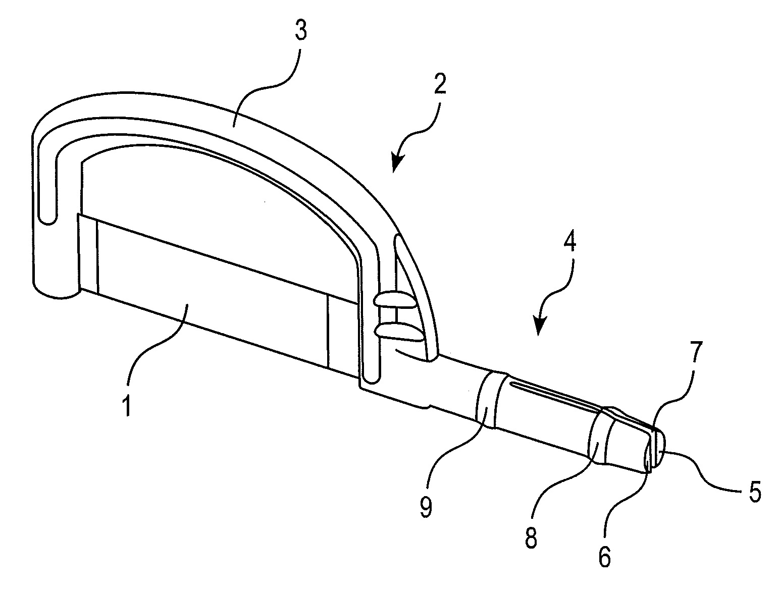
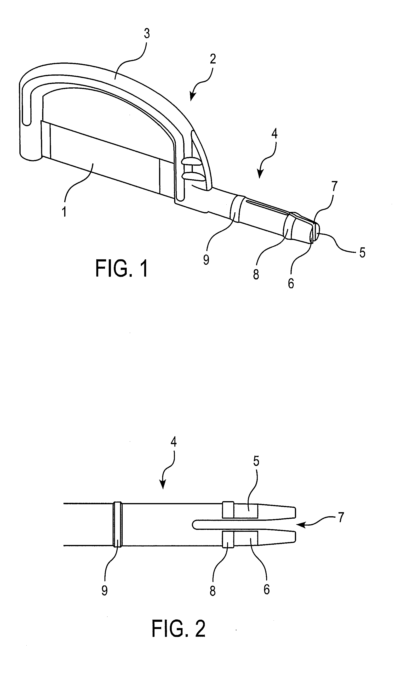
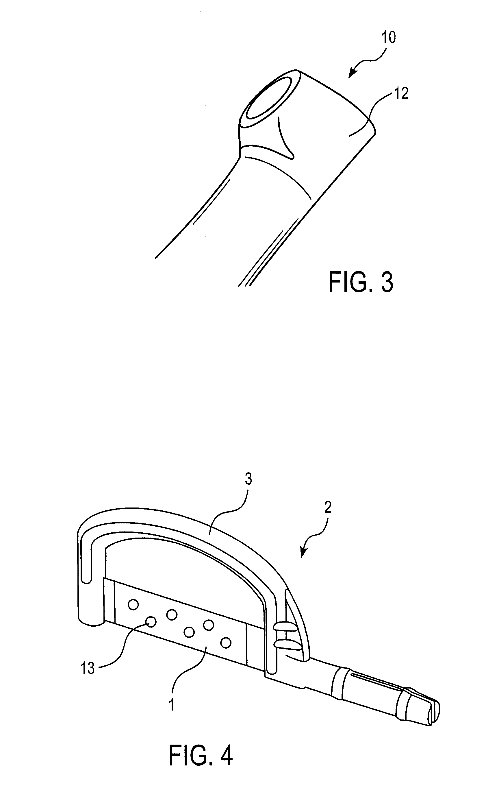
[0020]According to the invention as shown in FIG. 1, a first embodiment of an apparatus for removing enamel or debris from a tooth includes a blade 1 having an abrasive surface on at least one side of blade 1 or abrasive surfaces on both sides of blade 1. The apparatus further comprises a handle portion 2. Blade 1 is mounted to a support portion 3 of handle portion 2. Support portion 3 is bracket-shaped and comprises first and second bracket ends to which blade 1 is connected with its respective end portions. Blade 1 can be mounted to support portion 3 in a moulding process or, alternatively, it can be mounted to support portion 3 with separate mechanical fasteners (not shown). A shank 4 is integrally formed in one piece with support portion 3 with the proximal end of shank 4 being connected to one bracket end. Shank 4 comprises a flexible shank portion having two flexible elements 5,6 separated by a slit 7. Slit 7 extends axially from the distal end of shank 4 along the flexible sh...


PUM


Abstract

An apparatus for removing enamel or debris from a tooth includes a blade having an abrasive surface and a handle portion. The handle portion includes a support portion for mounting the blade and a shank having a proximal end connected to the support portion and a distal end. The shank includes a flexible shank portion having two flexible elements separated by a slit extending axially from the distal end of the shank along the flexible shank portion.

Description

TECHNICAL FIELD[0001]The invention relates to the field of dentistry or orthodontics, and in particular relates to an apparatus for removing enamel or debris from a tooth.BACKGROUND[0002]Apparatuses for removing enamel from a person's tooth are known in the field of dentistry or orthodontics. For example, they serve in removing enamel from one or more adjacently arranged teeth for the purpose of creating space, or additional space, between overcrowded teeth to avoid one or more tooth extractions. In other applications enamel is removed to enhance the shape and appearance of a tooth or of several teeth, for example for aesthetic reasons. In still further applications of such apparatuses debris like plaque or calculus can be removed from one or more teeth.[0003]Many devices are known which are suitable to remove enamel both for the purpose of interproximal enamel reduction as well as for forming tooth-contours. These devices typically comprise a blade having an abrasive surface. To re...

Claims


Application Information

Patent Timeline
IPC IPC(8): A61C17/00
CPCA61C3/06A61C3/12
Inventor REK, PETER
Owner SDC SWITZERLAND
Why Eureka
Try Eureka