
Device and method for determining the position of an instrument in relation to medical images

Active Publication Date: 2012-10-11
IMACTIS
View PDF4 Cites 57 Cited by
  • Summary
  • Abstract
  • Description
  • Claims
  • Application Information

AI Technical Summary

Benefits of technology

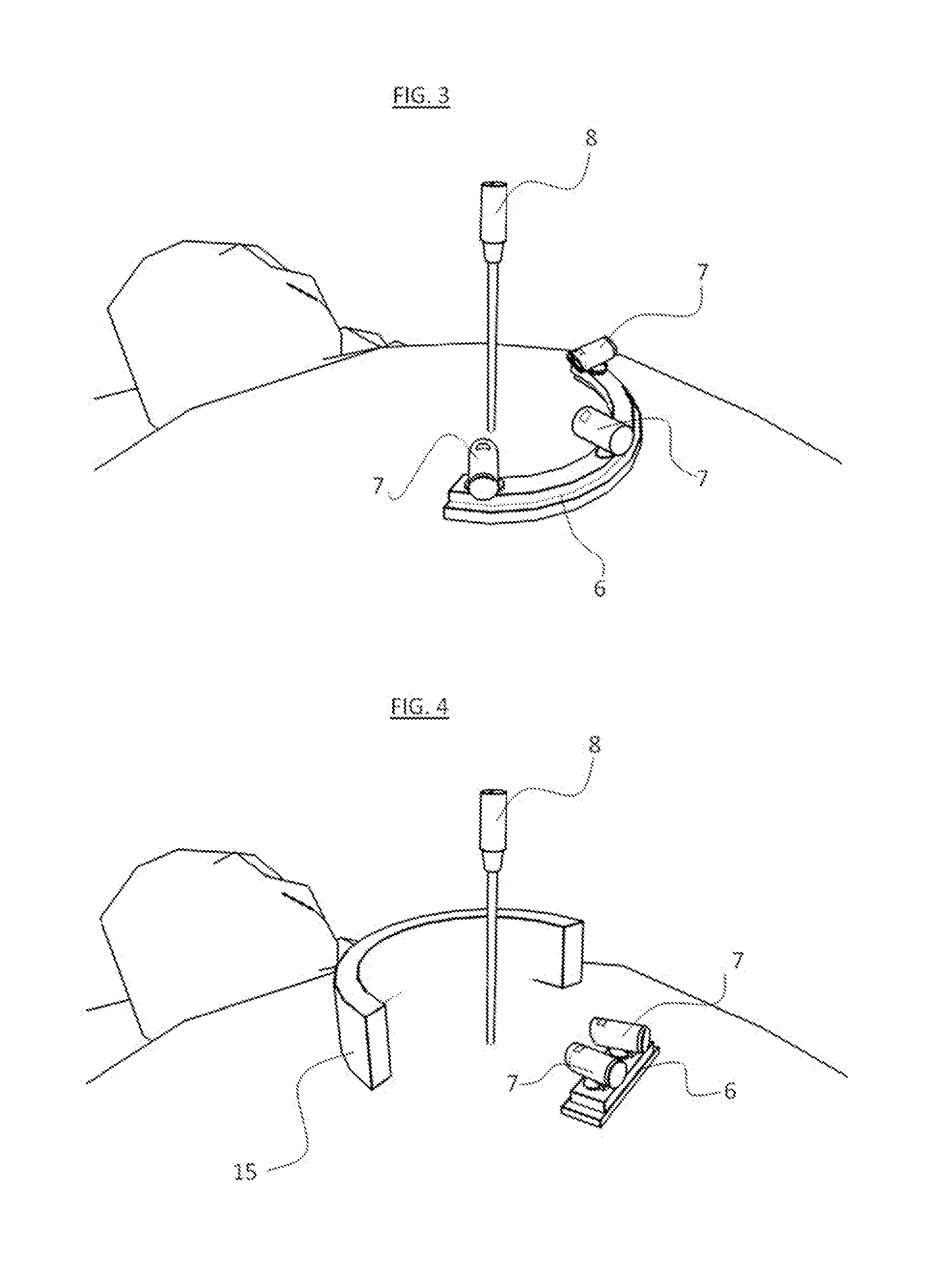
[0045]The device further advantageously comprises a background support adapted to be attached to the skin of the body and contrasting with the instrument to reinforce the visibility of the instrument on the video images.
[0048]In this case, the circular and rigid ring advantageously comprises a background cylinder contrasting with the instrument so as to reinforce the visibility of the instrument on the video images.
[0060]The micro-cameras may be equipped with a lighting system adapted to light the instrument so as to reinforce the visibility of the instrument on the video images.

Problems solved by technology

Existing optical localization devices are expensive and cumbersome, or not accurate enough.
(Waterloo, Ontario Canada) are compact but they are expensive; in addition, they require special care in environments with the presence of metallic objects such as the examination table or magnetic objects that constitute the core of magnetic resonance imaging devices, which may lead to inaccurate measurements.
But this device requires equipping a needle with cameras which adds weight to the needle and that operators do not appreciate.
In addition, if a micro-camera is mounted on a needle, the positions of the fingers and hands must be such to avoid the occlusions of the reference phantom, which adds complexity instead of providing a simple assistance to the operator.
However, those algorithms provide basic tools and components that any system in computer vision uses commonly, but they fail to provide a solution to the specific problem mentioned above.

Method used


Image

  • Device and method for determining the position of an instrument in relation to medical images
  • Device and method for determining the position of an instrument in relation to medical images
  • Device and method for determining the position of an instrument in relation to medical images

Examples


Embodiment Construction

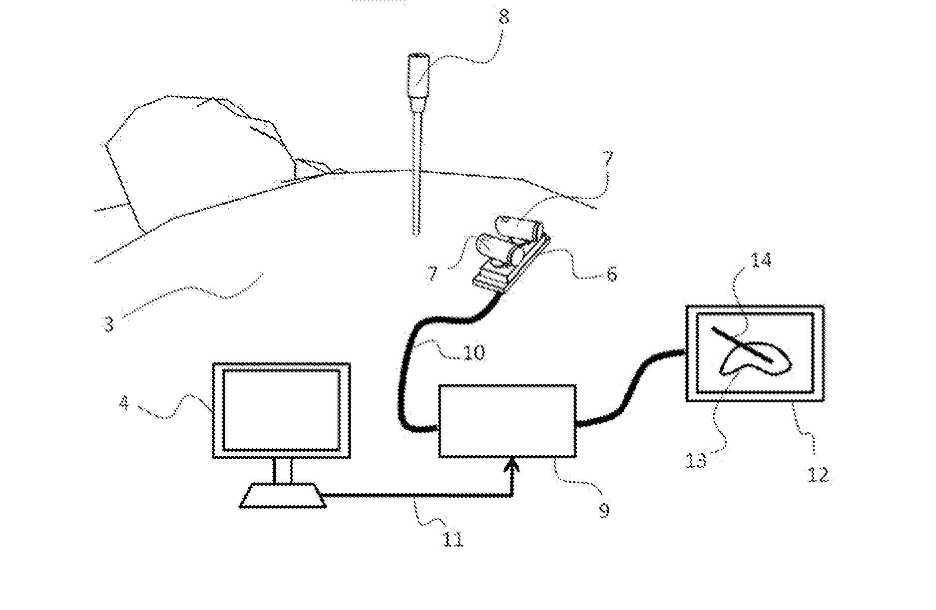
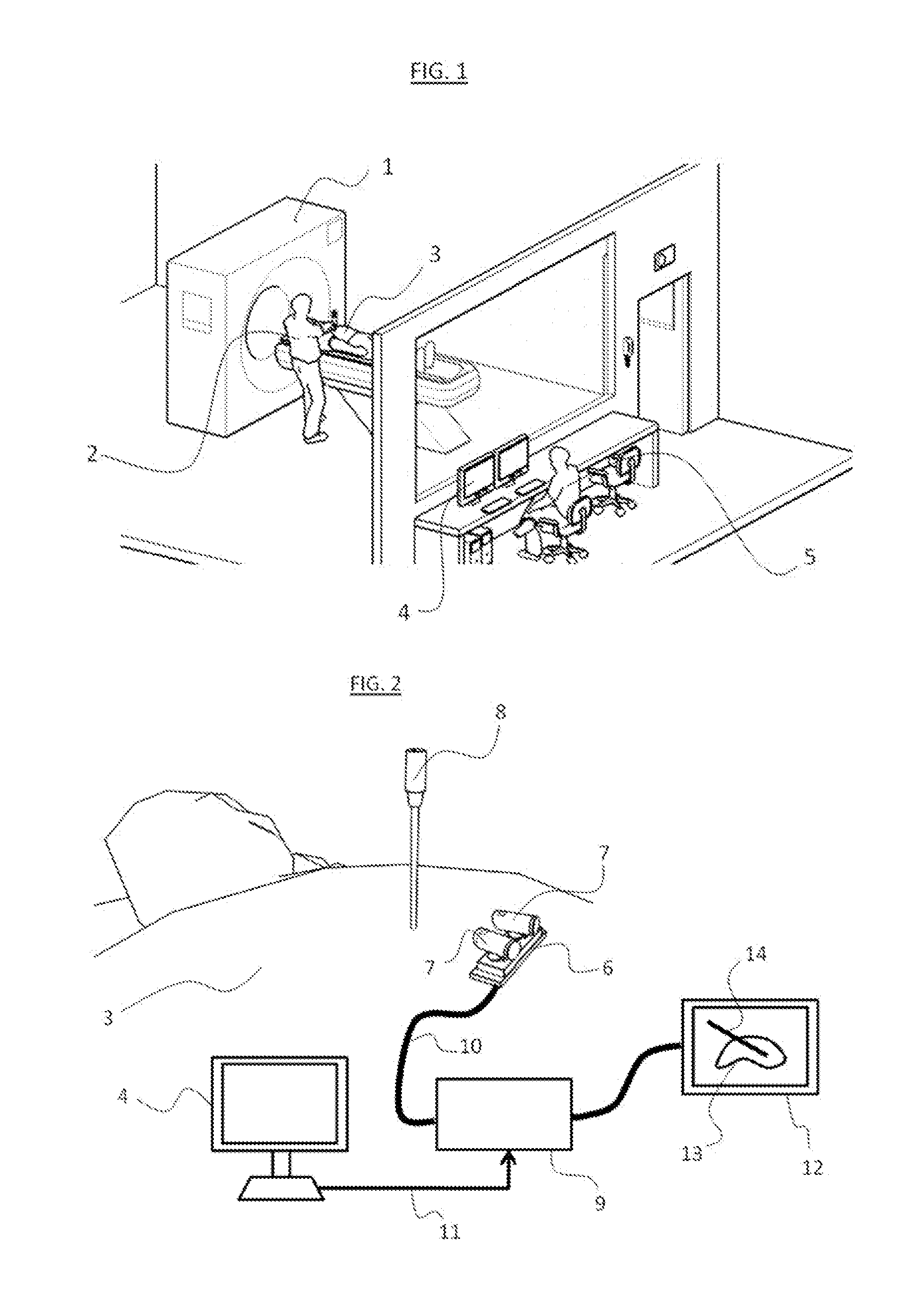
[0093]The present invention provides a device and method for tracking the position of a hand-held conventional instrument with respect to medical images of a body. The instrument is generally a needle or a linear guide to insert a needle like a surgical trocar. The rest of the text uses the term “instrument” to refer to a sharp and thin long instrument that is inserted into a body for delivering or extracting materials or energy, like biopsy trocars, needles, e.g. injection needles, radio-frequency probes, cryogenics probes, drains, K-wires, and rigid or semi-rigid trocars. The principles and operations of the device and method according to the present invention may be better understood with reference to the drawings and the accompanying description.

[0094]The present invention provides a device and a method for measuring the position and orientation of an instrument, which can be straight or bended, with respect to medical images of a body. A calibration support comprising a set of ...


PUM


Abstract

The present invention relates to a device and a method for determining the position of an instrument with respect to medical images of a body. The device comprises (1) a calibration support comprising a set of fiducial markers visible on medical images and fixed to the skin of a body, (2) at least one micro-camera providing video images and mounted on the calibration support in a known position, and (3) a processing unit connected to the micro-cameras and configured to process the video images from said micro-cameras to determine the position of the instrument with respect to medical images.

Description

CROSS REFERENCE TO RELATED APPLICATION[0001]This application claims priority to U.S. Provisional Application No. 61 / 473,235, filed Apr. 8, 2011, the content of which is incorporated herein by reference in its entirety.BACKGROUND[0002]1. Field of the Invention[0003]The present invention relates to a device and a method for determining the position of an instrument in relation to medical images.[0004]2. Description of Related Art[0005]Navigation systems are commonly tracking instrument position and orientation with respect to medical images of a body. Conventional tracking devices are made of optical devices, magnetic devices, ultrasonic devices, inclinometers, and accelerometers, radio-frequency measurement devices, used independently or in combination. In optical systems, tracking the position of an instrument is usually achieved by placing emitters or reflectors on both the instrument and on the body reference and observing the scene with two or three cameras. The most widely used ...

Claims


Application Information

Patent Timeline
IPC IPC(8): A61B6/12A61B5/055A61B6/02A61B6/03
CPCA61B5/061A61B6/032A61B6/12A61B6/487A61B19/04A61B19/5202A61B6/584A61B19/5244A61B2017/00438A61B2017/00725A61B2019/5227A61B2019/5289A61B2019/5437A61B19/5212A61B34/20A61B42/00A61B90/30A61B90/361A61B2090/364A61B2090/371A61B2090/3937
Inventor CARRAT, LIONELLAVALLEE, STEPHANIE
Owner IMACTIS
Learn More