Demand response system and method using a smart portal

a demand response and portal technology, applied in the field of demand response systems and methods using smart portals, can solve the problems of insufficient active customer motive, limited provided information, and small amount of actual bill reduction

Active Publication Date: 2012-10-11
SK TELECOM CO LTD
View PDF4 Cites 13 Cited by
  • Summary
  • Abstract
  • Description
  • Claims
  • Application Information

AI Technical Summary

Problems solved by technology

However, information generated by all the smart grid systems is various, and the amount of reduction of an actual bill is not great.
I...

Method used


Image

  • Demand response system and method using a smart portal
  • Demand response system and method using a smart portal
  • Demand response system and method using a smart portal

Examples


Embodiment Construction

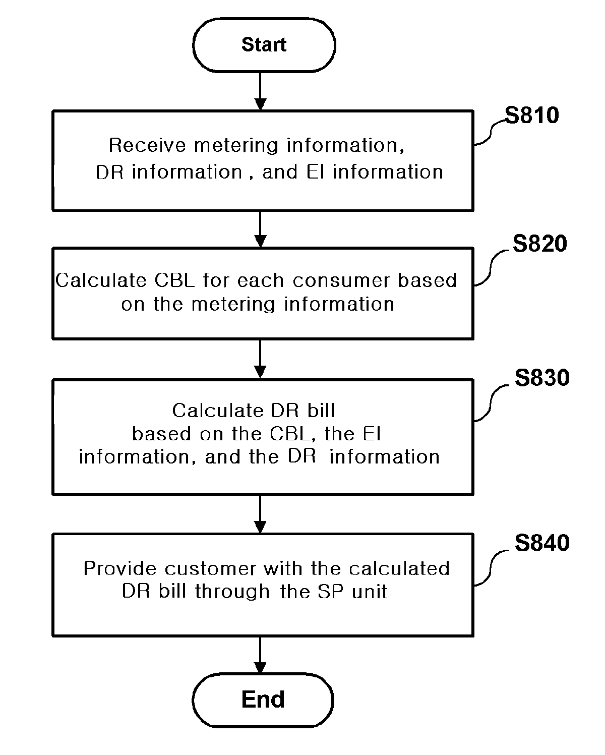
[0037]An embodiment of the disclosure and detailed contents of the descriptions about technical configurations and the operational effects thereof will be more clearly understood from the following detailed description based on the drawings attached in the specification of the disclosure. Embodiments of the disclosure are described in detail below with reference to the attached drawings.

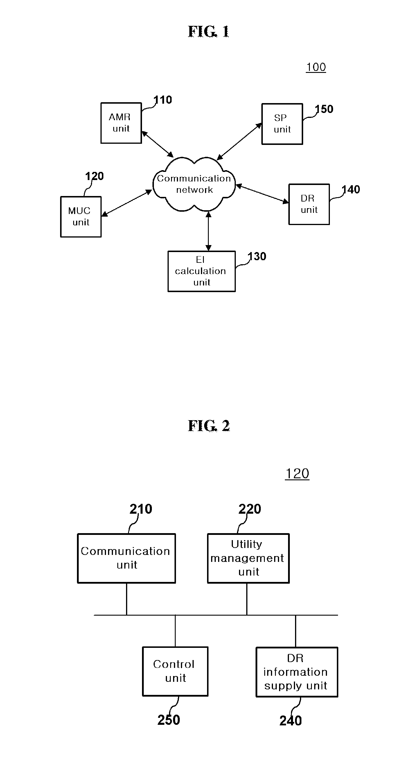
[0038]FIG. 1 is a configuration diagram showing the entire construction of a demand response system using a smart portal according to an embodiment of the disclosure.

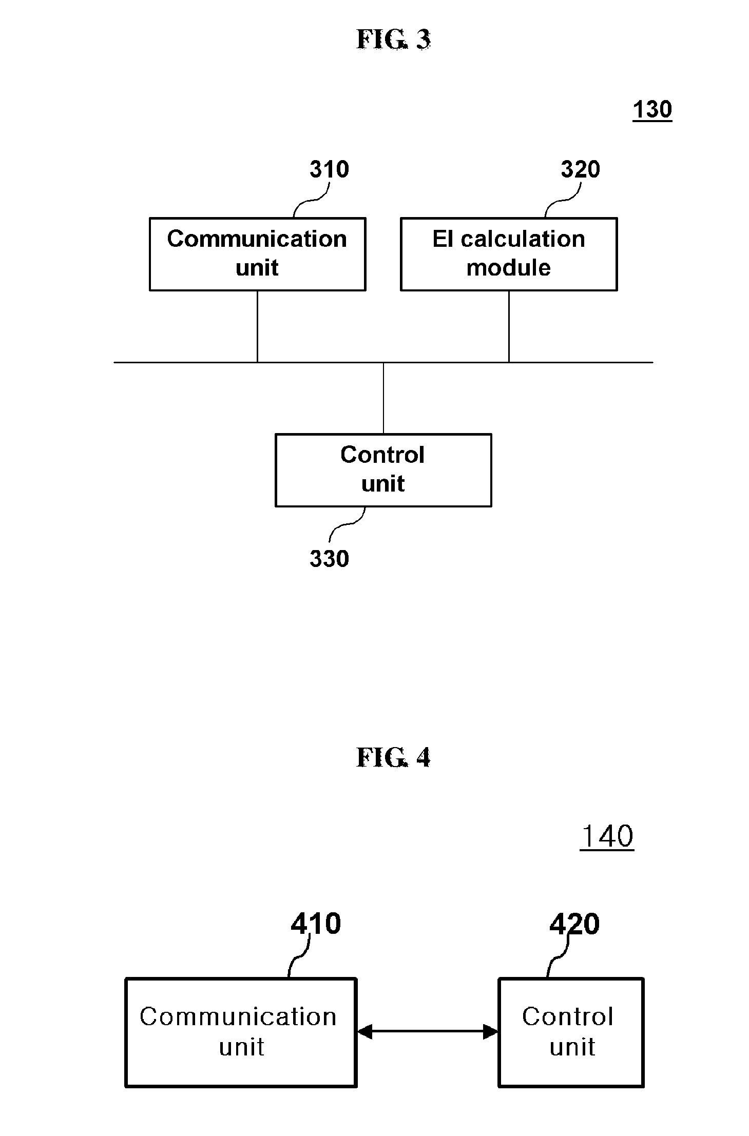
[0039]Referring to FIG. 1, the demand response system 100 using a smart portal according to the embodiment includes an Automatic Meter Reading (hereinafter referred to as an ‘AMR’) unit 110, a Multi Utility Complex (hereinafter referred to as an ‘MUC’) unit 120, an Eco Index (hereinafter referred to as an ‘EI’) calculation unit 130, a DR unit 140, and a Smart Portal (hereinafter referred to as an ‘SP’) unit 150.

[0040]The AMR unit 110 gen...


PUM


Abstract

The demand response system comprises an automatic meter reading (AMR) unit to generate metering information. The demand response system comprises a multiple utility complex unit (MUC) which provides DR information based on the metering information and manages utility supply schedule in combination. The demand response system comprises an eco index (EI) calculation unit which calculates an eco index based on the metering information. The demand response system comprises a demand response (DR) unit which obtains the CBL information based on the metering information and computes a the DR bill by using the CBL data, the DR information and EI obtained, and outputs the DR bill. The demand response system comprises a smart portal (SP) unit which provides users with the calculated DR bill. According to the disclosure, the demand response system can provide environmental and social information, in addition to economic information.

Description

TECHNICAL FIELD [0001]The disclosure relates to a demand response system and method using a smart portal in order to combine and manage utilities, such as water / sewage, gas, electricity, and heating / air-conditioning, within a local area. More particularly, the disclosure relates to a demand response system and method using a smart portal, which calculate a Customer Baseline Load (hereinafter referred to as a ‘CBL’) based on the analysis of usage data and provides a customer with information on a DR billing plan for a utility use by taking the calculated CBL into consideration via a smart portal such that the customer can control the utilities' demand for himself in order to efficiently manage user demands by changing the existing utility ‘supply’ system (i.e., ‘billing for the past use’) into a utility ‘purchase’ system (i.e., ‘pre-billing for the future use’).BACKGROUND [0002]The existing utilities, such as water / sewage, electricity, gas, and heating / air-conditioning, have been rec...

Claims


Application Information

Patent Timeline
IPC IPC(8): G06Q30/04G06Q30/00
CPCY04S50/14G06Q30/02G06Q50/06
Inventor PARK, KYOUNG MINPARK, JI YOUNGPARK, WOO YOUNGKIM, TAE HUN
Owner SK TELECOM CO LTD
Why Eureka
Try Eureka