Method and tooling for manufacture of co-cured composite structures

a composite structure and tooling technology, applied in the field of cocuring composite stringers, can solve the problems of difficulty in maintaining the smoothness and pressure desired

Active Publication Date: 2012-10-18
SPIRIT AEROSYSTEMS
View PDF3 Cites 18 Cited by
  • Summary
  • Abstract
  • Description
  • Claims
  • Application Information

AI Technical Summary

Benefits of technology

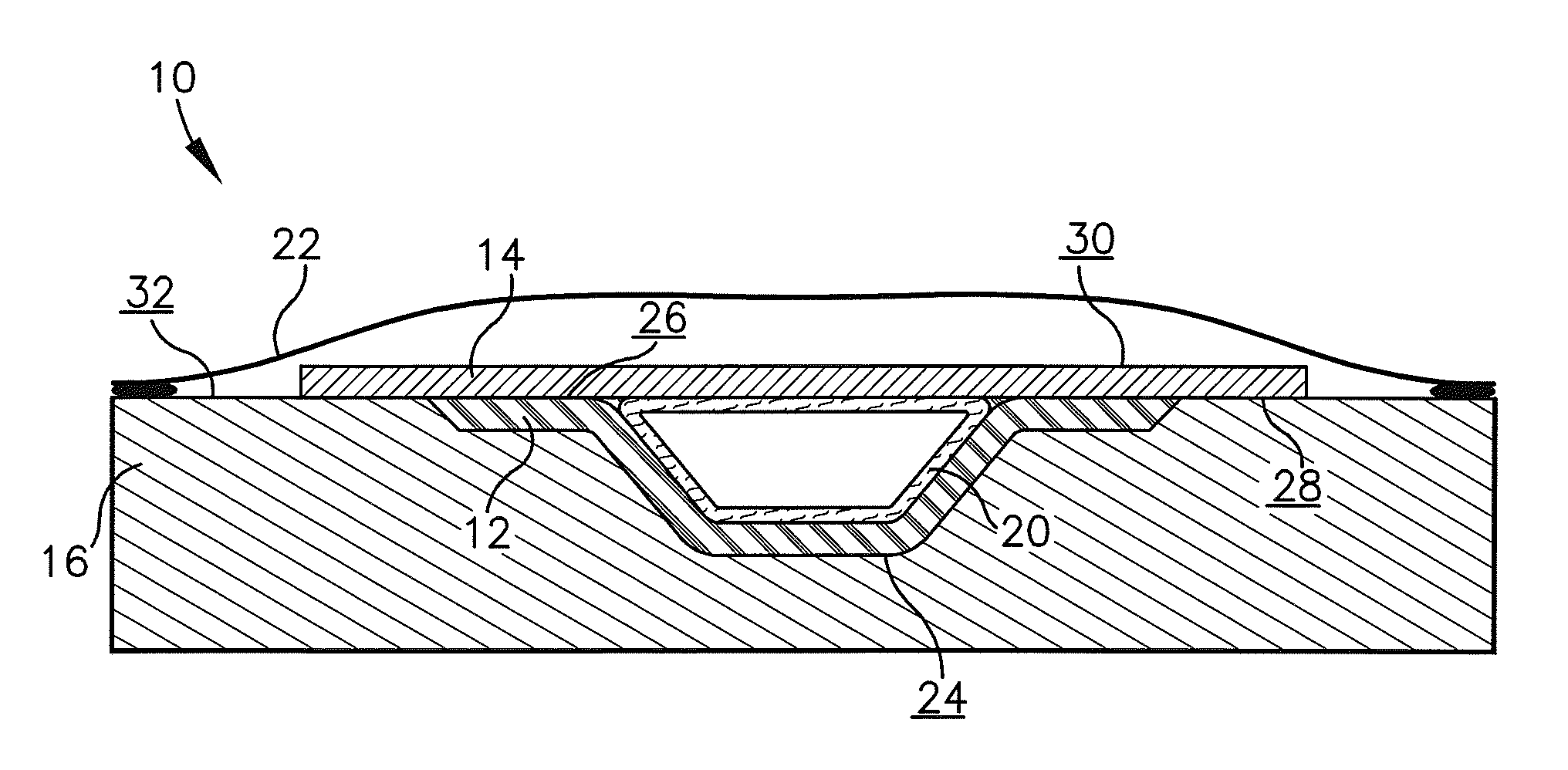
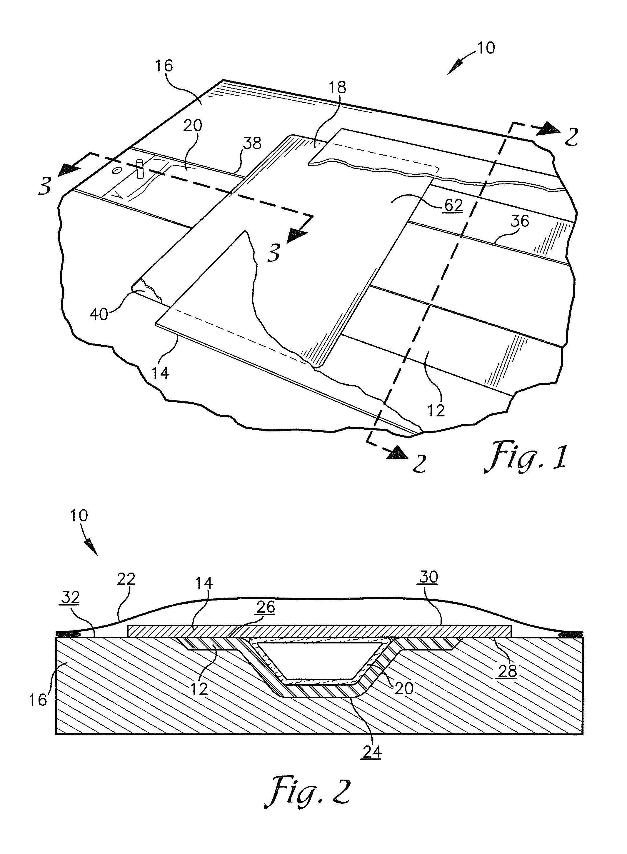
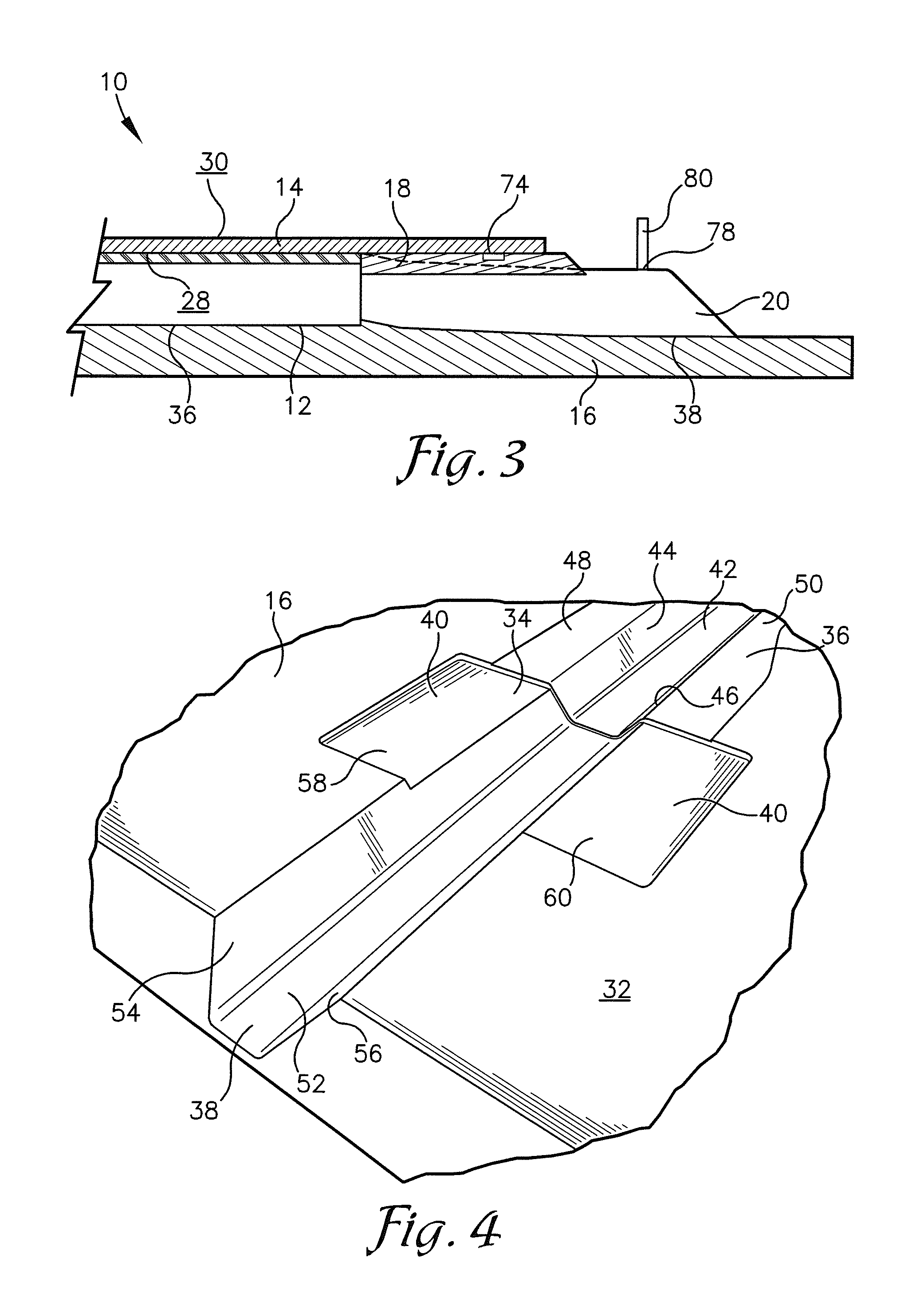
[0010]The forming tool may comprise a top surface and cavities formed into the top surface. The cavities may comprise an elongated material trough, a bladder extension trough laterally aligned with and open to the material trough, and a recessed pocket. The material trough may comprise a bottom wall, two side walls extending upward from the bottom wall, and two flange recesses extending outward from the side walls. The bladder extension trough may...

Problems solved by technology

Because the bladder is being vented in the vicinity of these f...

Method used


Image

  • Method and tooling for manufacture of co-cured composite structures
  • Method and tooling for manufacture of co-cured composite structures
  • Method and tooling for manufacture of co-cured composite structures

Examples


Embodiment Construction

[0025]The following detailed description of the invention references the accompanying drawings that illustrate specific embodiments in which the invention can be practiced. The embodiments are intended to describe aspects of the invention in sufficient detail to enable those skilled in the art to practice the invention. Other embodiments can be utilized and changes can be made without departing from the scope of the present invention. The following detailed description is, therefore, not to be taken in a limiting sense. The scope of the present invention is defined only by the appended claims, along with the full scope of equivalents to which such claims are entitled.

[0026]In this description, references to “one embodiment”, “an embodiment”, or “embodiments” mean that the feature or features being referred to are included in at least one embodiment of the technology. Separate references to “one embodiment”, “an embodiment”, or “embodiments” in this description do not necessarily ref...


PUM

PropertyMeasurementUnit
Thicknessaaaaaaaaaa
Widthaaaaaaaaaa
Impermeabilityaaaaaaaaaa

Abstract

A method and part forming apparatus configured for forming an aircraft stringer. The part forming apparatus may comprise a forming tool, a rigid plate, and a hollow bladder. The forming tool may comprise a material trough, a bladder extension trough laterally aligned with and open to the material trough, and a recessed pocket extending from either side of the bladder extension trough and adjacent to the material trough. The method comprises placing composite material into the material trough, placing the bladder onto the composite material and through the bladder extension trough, placing the rigid plate into the recessed pocket and over the bladder, and then placing skin laminate over the bladder and the composite material. Once each of these components is in place, the forming tool may be vacuum bagged and the composite material and skin laminate may be co-cured to form the stringer.

Description

BACKGROUND[0001]1. Field[0002]Embodiments of the present invention relate to a method and apparatus for co-curing composite stringers.[0003]2. Related Art[0004]Aircraft stringers are elongated, thin strips of wood, metal, or carbon fiber to which a skin of an aircraft is fastened. For example, stringers can be attached within nacelles, fuselages, or wings of an aircraft to provide strength and support to the structure. Until recently, most stringers have been formed of metal. Now many stringers are formed of composite materials to reduce the aircrafts weight.[0005]Some composite stringers are hollow and have a substantially trapezoid-shaped cross-section, which may be fixed or cured to a skin laminate. Furthermore, the skin laminate may serve as one of the stringer's walls. The skin laminate wall is typically wider and longer than the rest of the stringer walls, forming a plurality of flanges extending in a plurality of directions outward from the stringer. These flanges are used to...

Claims


Application Information

Patent Timeline
IPC IPC(8): B29C70/44
CPCB29C70/44Y10T156/10B29D99/0014
Inventor BERGMANN, BLAISE F.SPAULDING, DWIGHT D.MCPHERSON, JOHN P.
Owner SPIRIT AEROSYSTEMS
Why Eureka
Try Eureka