Residential electric power storage system

a technology of electric power storage and residential buildings, applied in the direction of battery/fuel cell control arrangement, transportation and packaging, greenhouse gas reduction, etc., can solve the problem of difficulty in storing generated electric power, and achieve the effect of increasing the life of the power storage devi

Active Publication Date: 2012-10-18
TOYOTA JIDOSHA KK
View PDF3 Cites 0 Cited by
  • Summary
  • Abstract
  • Description
  • Claims
  • Application Information

AI Technical Summary

Benefits of technology

[0023]The present invention can thus provide a residential electric power storage system allowing a residence equipped therewith to have an electric power storage device electrically discharging suitably to the residence and therefore the lifetime of the power storage device increases.

Problems solved by technology

It is difficult to store generated electric power, and accordingly, electric power generation facilities have their capabilities set to generate electric power in accordance with a peak of demand for electric power.

Method used


Image

  • Residential electric power storage system
  • Residential electric power storage system
  • Residential electric power storage system

Examples


Embodiment Construction

[0036]Hereinafter reference will be made to the drawings to describe the present invention in embodiments. In the figures, identical or corresponding components are identically denoted, and will thus not be described repeatedly.

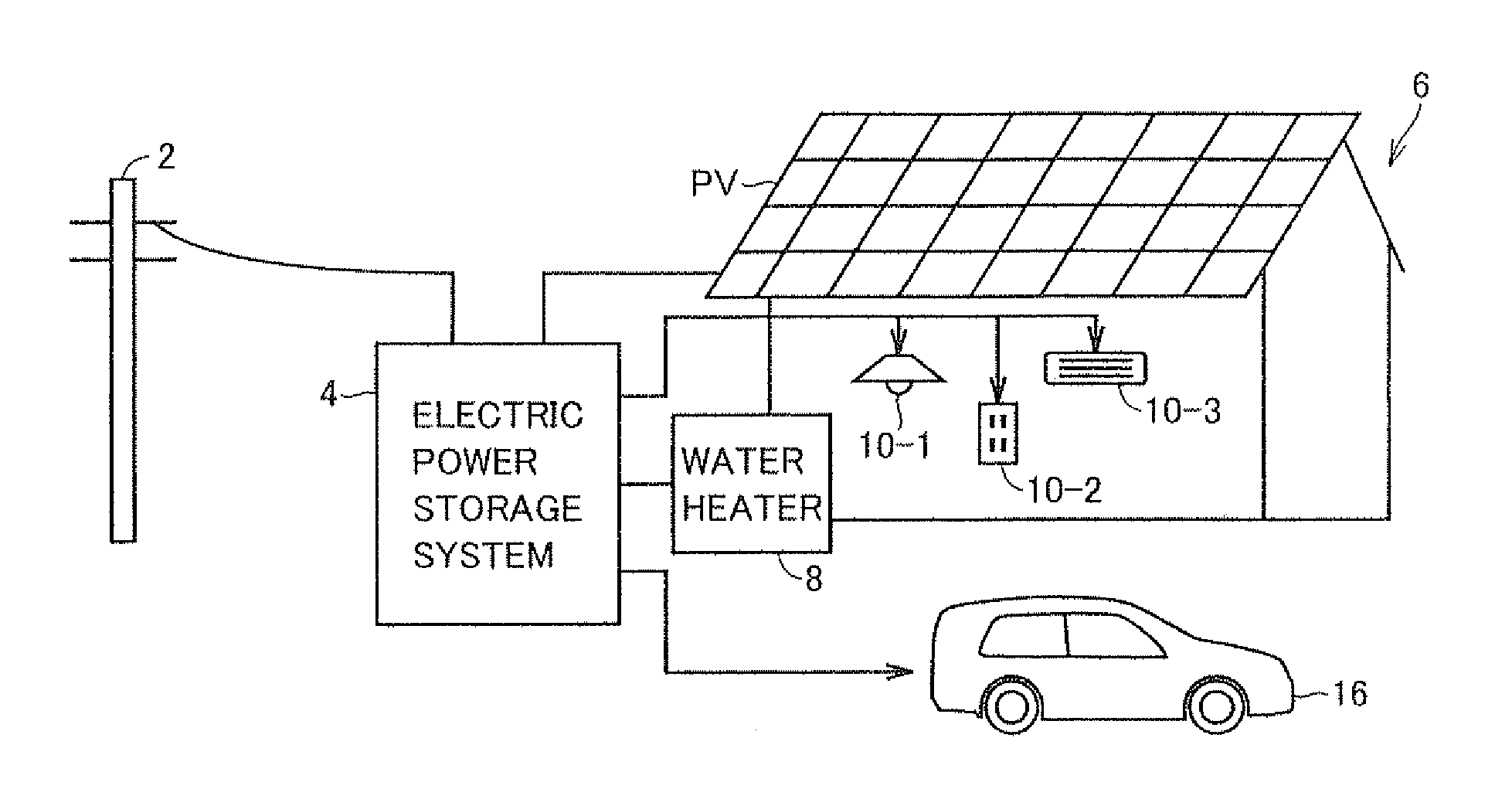
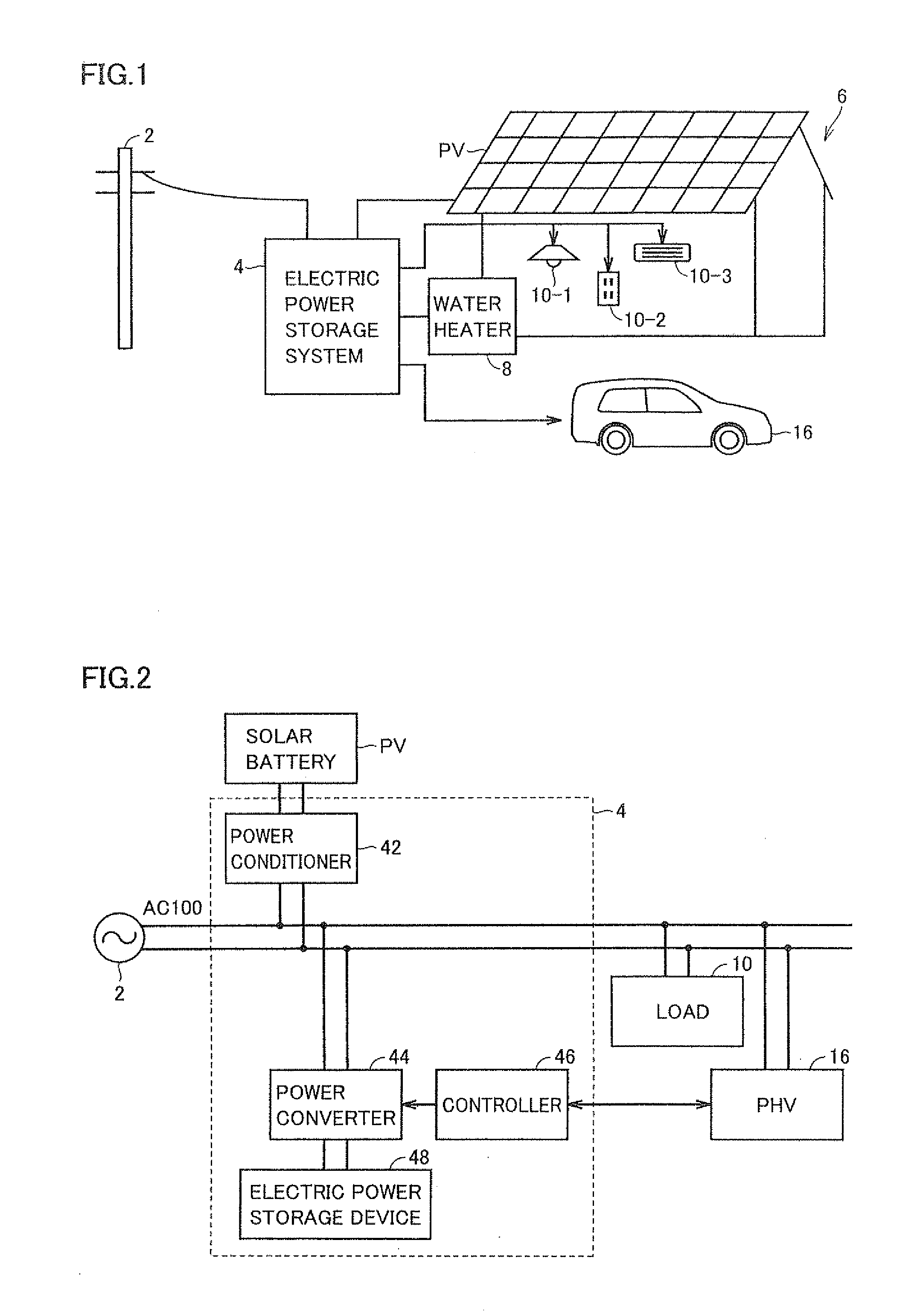
[0037]FIG. 1 is a diagram for outlining a residential electric power storage system.

[0038]With reference to FIG. 1, an electric power storage system 4 is installed in a residence 6. Electric power storage system 4 has connected thereto a commercial power supply 2, a solar battery PV, a household electrical load 10 (including illumination 10-1, a plug outlet 10-2, an air conditioner 10-3, and the like), an electric water heater 8, and a vehicle 16. Vehicle 16 is a plug-in hybrid vehicle having an externally electrically chargeable battery or the like mounted therein. Note that vehicle 16 may be an electric vehicle or a fuel cell powered vehicle, for example.

[0039]FIG. 2 is a block diagram for illustrating a configuration of electric power storage system 4.

[004...


PUM


Abstract

A controller includes a data accumulation unit that obtains data of an amount of electric power consumed in a residence and accumulates the obtained data a representative pattern creation unit that creates a representative pattern based on the data accumulated in the data accumulation unit, the pattern representatively indicating how the electric power storage device varies in state of charge for its discharging period and a limit value determination unit that determines a limit value to correspond to the pattern.

Description

TECHNICAL FIELD[0001]The present invention relates to a residential electric power storage system, and particularly to controlling an amount of electric power discharged from an electric power storage device.BACKGROUND ART[0002]While there is a smaller demand for electric power late at night than daytime, it is better to operate an electric power generator continuously, because doing so is more efficient. It is difficult to store generated electric power, and accordingly, electric power generation facilities have their capabilities set to generate electric power in accordance with a peak of demand for electric power. Under such a circumstance, it is well known that late-night power rate is lower than daytime power rate. It is desirable if households, companies, factories, and other electric power consumers can store midnight electric power in a reservoir type storage battery and use it in the daytime to achieve a reduced electricity bill and a leveled load.[0003]Japanese Patent Layi...

Claims


Application Information

Patent Timeline
Patent Type & Authority Applications(United States)
IPC IPC(8): H02J7/00
CPCH02J3/32H02J7/35Y04S10/126B60L55/00B60L58/14B60L58/13B60L53/51H02J2310/48H02J2300/24H02J3/381Y02B10/10Y02E10/56Y02E60/00Y02T10/70Y02T10/7072Y02T90/12H02J3/466Y02T90/14Y02E70/30Y02T90/16
Inventor ICHIKAWA, SHINJI
Owner TOYOTA JIDOSHA KK
Why Eureka
Try Eureka