

Wristwatch
a wristwatch and wrist technology, applied in the field of wristwatches, can solve the problems of agitation of liquid, difficulty in transposing to a wristwatch, absence of dimensions of pumps, etc., and achieve the effect of reducing energy loss and interesting animation
- Summary
- Abstract
- Description
- Claims
- Application Information
AI Technical Summary
Benefits of technology
Problems solved by technology
Method used
Image

Examples
Embodiment Construction
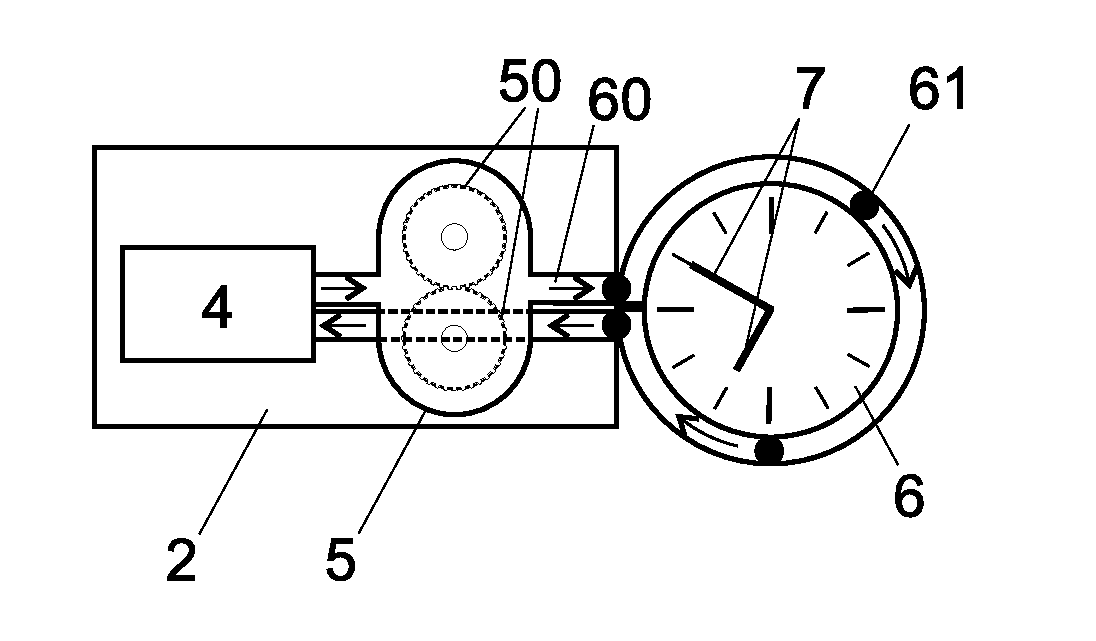
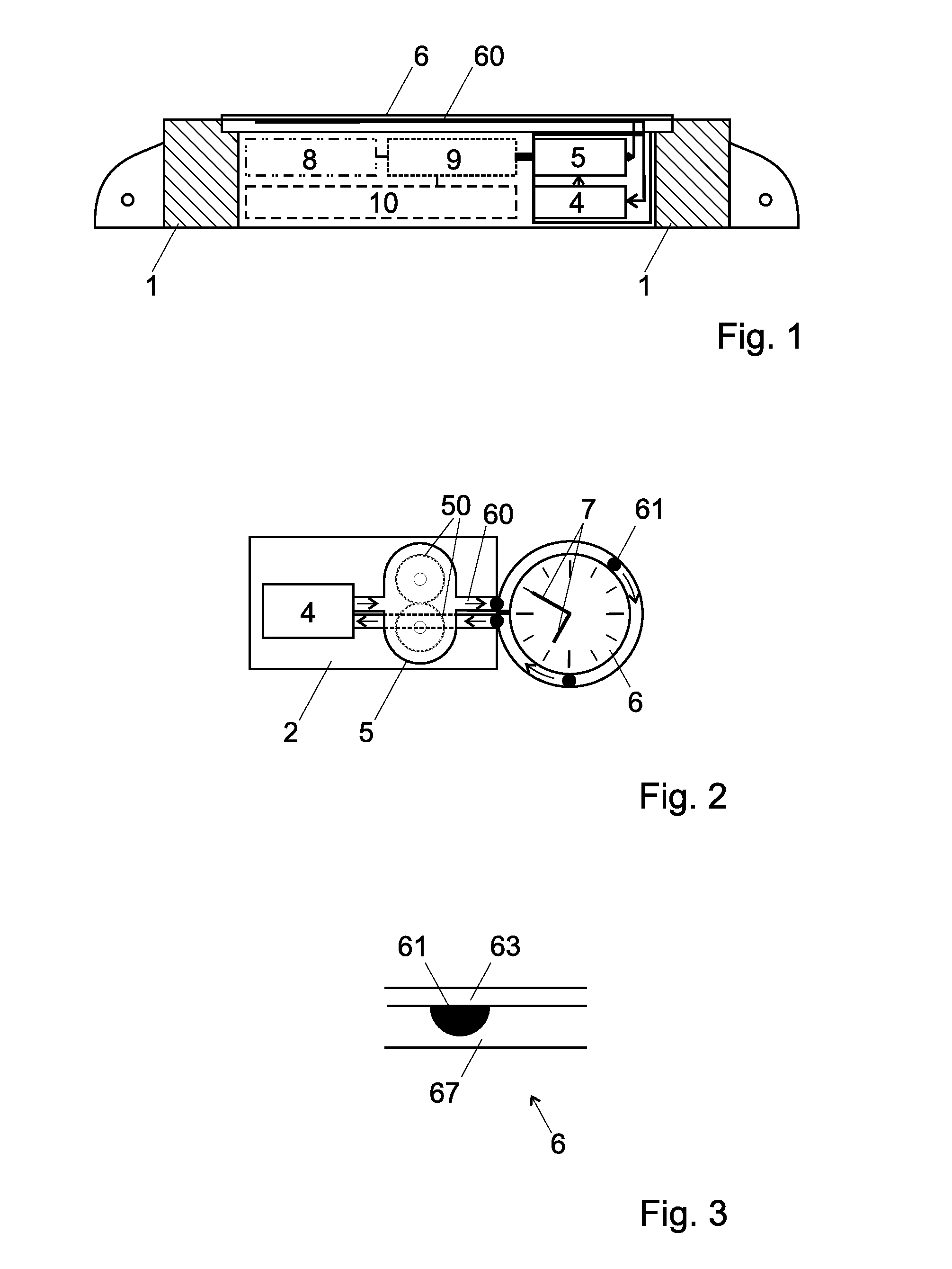
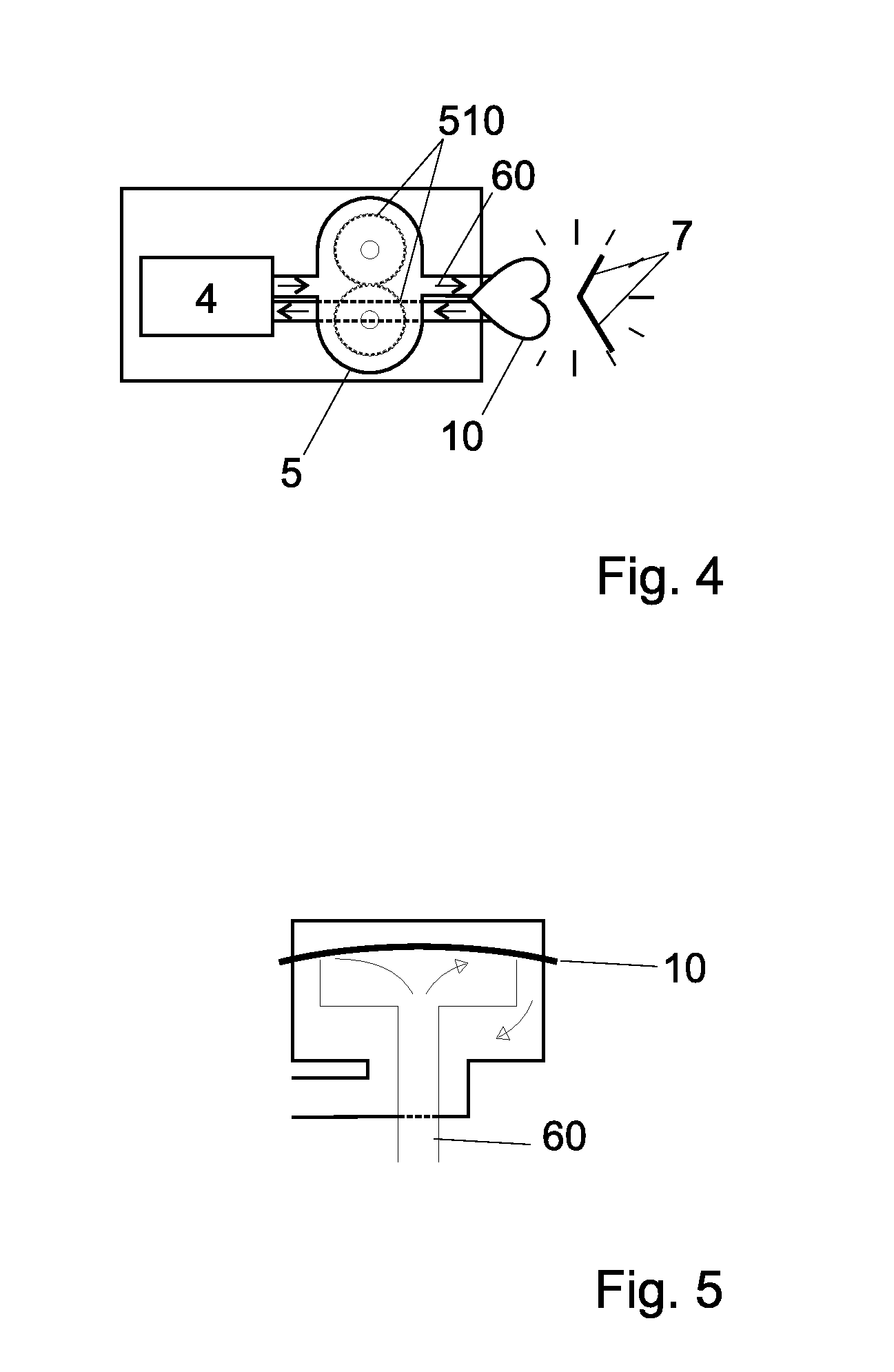
[0054]FIG. 1 is a simplified cross sectional view of a wristwatch according to the invention. Another embodiment of a wristwatch according to the invention is also illustrated in a top view in FIG. 6. The watch advantageously comprises in a case 1 a fluid distributor 2 with a reservoir 4 and a pump 5. The pump 5 is advantageously a gear pump provided with two wheels 50 with an external teething, or an inside gear pump that has lower space requirements. The gear pump is driven by the watch movement 8-9-10 which also determines its rotational speed. The carter 52 of the pump 5 is preferably transparent and can be made of synthetic material or of glass, in order to show the gears rotating and the liquid being driven. In one embodiment, the carter is made from several sheets of glass or transparent material superimposed one upon another. The sheets are preferably welded to one another and to the channels by high temperature fusion. The gearings 50 are held in this carter 52 by staffs 50...
PUM
| Property | Measurement | Unit |
|---|---|---|
| diameter | aaaaa | aaaaa |
| diameter | aaaaa | aaaaa |
| transparent | aaaaa | aaaaa |
Abstract
Description
Claims
Application Information