
Line Receptacle Device with Strain Relief

a line receptacle and strain relief technology, applied in the direction of coupling device connection, coupling/disconnecting parts, electrical apparatus, etc., can solve the problem of increasing the time required to install a cable or a line into such a line receptacle device, and achieve the effect of simplifying the installation of such line receptacles, improving the conventional line receptacle devices, and less time to install

Active Publication Date: 2012-10-18
SIEMENS AG
View PDF5 Cites 3 Cited by
  • Summary
  • Abstract
  • Description
  • Claims
  • Application Information

AI Technical Summary

Benefits of technology

[0005]It is an object of the present invention to improve conventional line receptacle devices to the extent that installation of such line receptacles is simplified and such that they require less time to install.
[0008]In a further embodiment, the locking device are configured as T-shaped catches and the retaining means as longitudinal slots with recesses at the first position. Here, the strain relief device has the locking device as a T-shaped catch and the housing parts each have a retaining device comprising longitudinal slots in the housing parts. In order, for example, to make it possible for the housing parts to be folded together when the strain relief device is located in the first position, the retaining device with its longitudinal slot has two recesses arranged transversely to the longitudinal slot which make it possible for the T-shaped catch to penetrate into the housing at the location of the recesses.
[0011]To use the line receptacle device, for example, for plug systems in electrical installations, the line receptacle device has a receptacle for receiving a plug connector. For particularly supplying power to electrical devices, especially in process automation, the line receptacle device with its plug connector in accordance with the invention can be used as a connection plug for power supply modules of a modular automation system. This type of line receptacle device enables simple, rapid installation or dismantling and easier wiring work to be implemented. The movable strain relief device provides a further advantage in that a range of possible cross sections of lines or individual wires can be covered. For example, the U-shaped embodiment of the strain relief device allows strain relief to be safely provided for 3 individual leads each of 1.5 mm2 up to an entire cable or a line with a total diameter of 9 mm.

Problems solved by technology

The use of at least two separate screw fitting mechanisms mean that increased time is required to install a cable or a line into such a line receptacle device.

Method used


Image

  • Line Receptacle Device with Strain Relief
  • Line Receptacle Device with Strain Relief
  • Line Receptacle Device with Strain Relief

Examples


Embodiment Construction

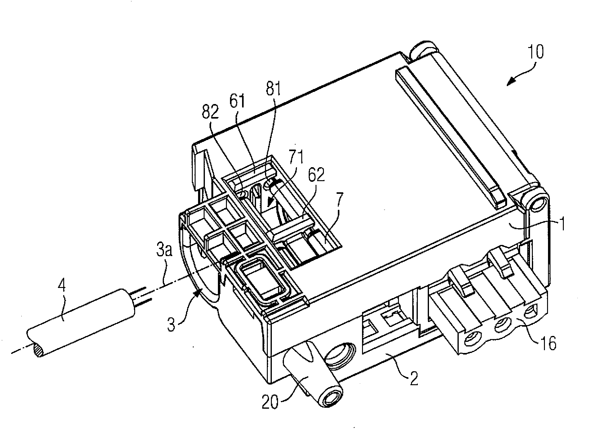
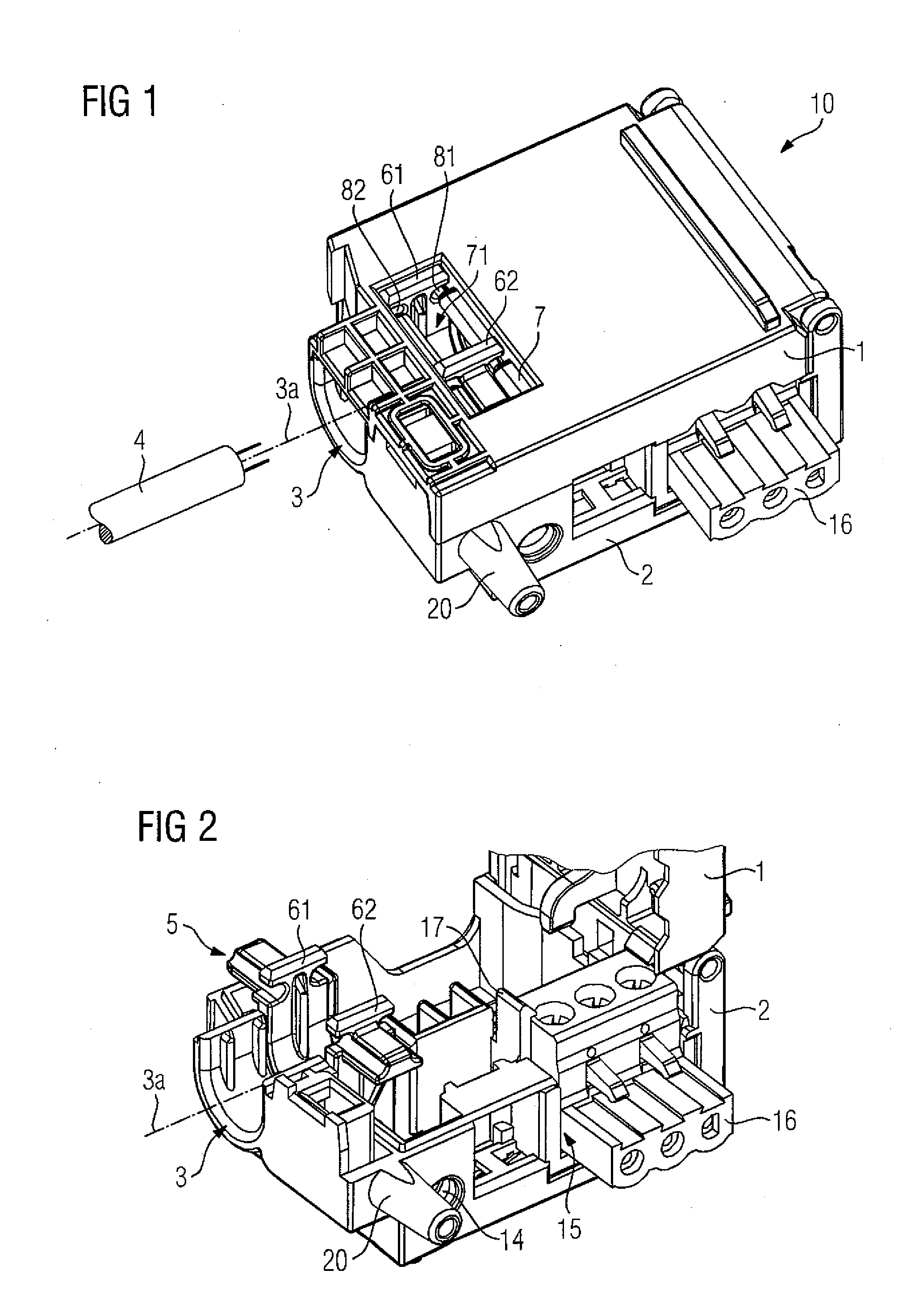
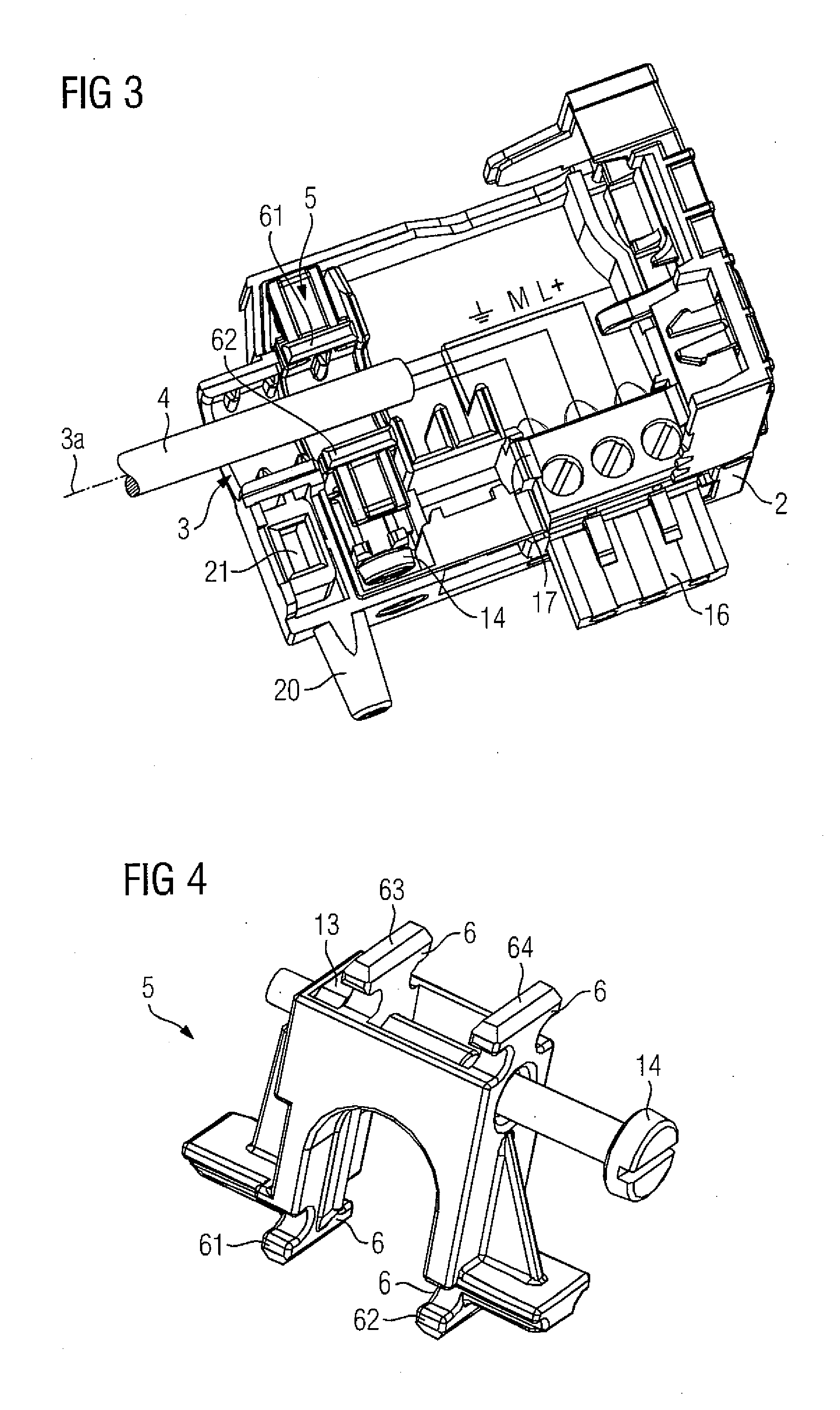
[0021]The diagram according to FIG. 1 shows a line receptacle device 10 comprising a connection plug for a power supply module of an automation system. The line receptacle device 10 comprises a first housing part 1, a second housing part 2, an entry channel 3 for a line 4 and a strain relief device 5, which is arranged to allow movement between the first housing part 1 and the second housing part 2. The first housing part 1 has a first longitudinal slot 71, whereby a first catch 61 which is configured in the shape of a T can penetrate transversely through a first recess 81 and a second recess 82 into the first longitudinal slot. The line 4 is introduced in parallel to a longitudinal axis 3a into the entry channel 3. A plug connector 16 with screw terminal connections is available for an electrical connection of individual leads.

[0022]FIG. 2 shows the connection plug of FIG. 1 in a slightly perspectively modified diagram, with the first housing part 1 opened. The strain relief device...


PUM


Abstract

A line receptacle device comprising a first housing part, a second housing part, an entry channel for a line and a strain relief device that is configured to move from a first position into a second position, and if configured such that, in the first position the line can be introduced through the entry channel and in the second position the line can be clamped into the entry channel, in which case the strain relief device also has a locking device which, on transition from the first position into the second position, interacts with a retaining device disposed in the first housing part and the second housing part such that the housing parts are locked together.

Description

BACKGROUND OF THE INVENTION[0001]1. Field of the Invention[0002]The invention relates line receptacles and, more particularly, to a line receptacle device comprising a first housing part, a second housing part, an entry channel for a line and a strain relief device.[0003]2. Description of the Related Art[0004]Conventional line receptacle devices known, for example, as a plug housing with strain relief are generally known, such as the Schuko plug system. In conventional solutions for providing strain relief, the line receptacle devices use at least two separate screw fittings, a first screw fitting for strain relief of the line, and a second screw fitting that is needed to close off a housing of the line receptacle device. The use of at least two separate screw fitting mechanisms mean that increased time is required to install a cable or a line into such a line receptacle device.SUMMARY OF THE INVENTION[0005]It is an object of the present invention to improve conventional line recept...

Claims


Application Information

Patent Timeline
IPC IPC(8): H01R13/62
CPCH01R13/508H01R13/595H01R13/5816
Inventor STEIN, ULF
Owner SIEMENS AG
Learn More