Sensor guide wire

a technology of guide wire and wire, applied in the direction of guide wire, sensors, medical science, etc., can solve the problems of bending artefacts, requiring extra machining or wire forming, loss of time and material in the manufacturing process, etc., and achieve the effect of easy and less expensive manufacturing

Inactive Publication Date: 2012-10-18
ST JUDE MEDICAL COORDINATION CENT
View PDF9 Cites 27 Cited by
  • Summary
  • Abstract
  • Description
  • Claims
  • Application Information

AI Technical Summary

Benefits of technology

[0011]Thus, there is a need for a sensor guide wire wherein the mounting of the sensor does not involve extra machining or wire forming, which thereby is easier and less expensive to manufacture.

Problems solved by technology

A potential problem with this kind of guide wire mounted sensors is the occurrence of so-called bending artefacts.
The cantilevered mounting of the sensor, however, requires extra machining or wire forming of the core wire at the site where the sensor chip is placed.
The careful machining of the core wire into different diameters at different portions of the guide wire is a time-consuming process and may be a source of manufacturing mistakes, leading to loss of time and material in the manufacturing process.

Method used


Image

  • Sensor guide wire
  • Sensor guide wire
  • Sensor guide wire

Examples


Embodiment Construction

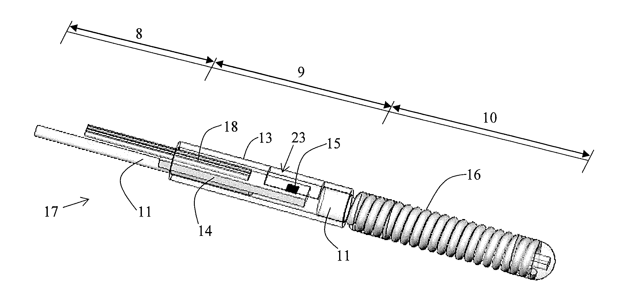
[0028]Throughout the application the word distal refers to the part located furthest away in respect of the operator, and the word proximal refers to the part located closest in respect of the operator.

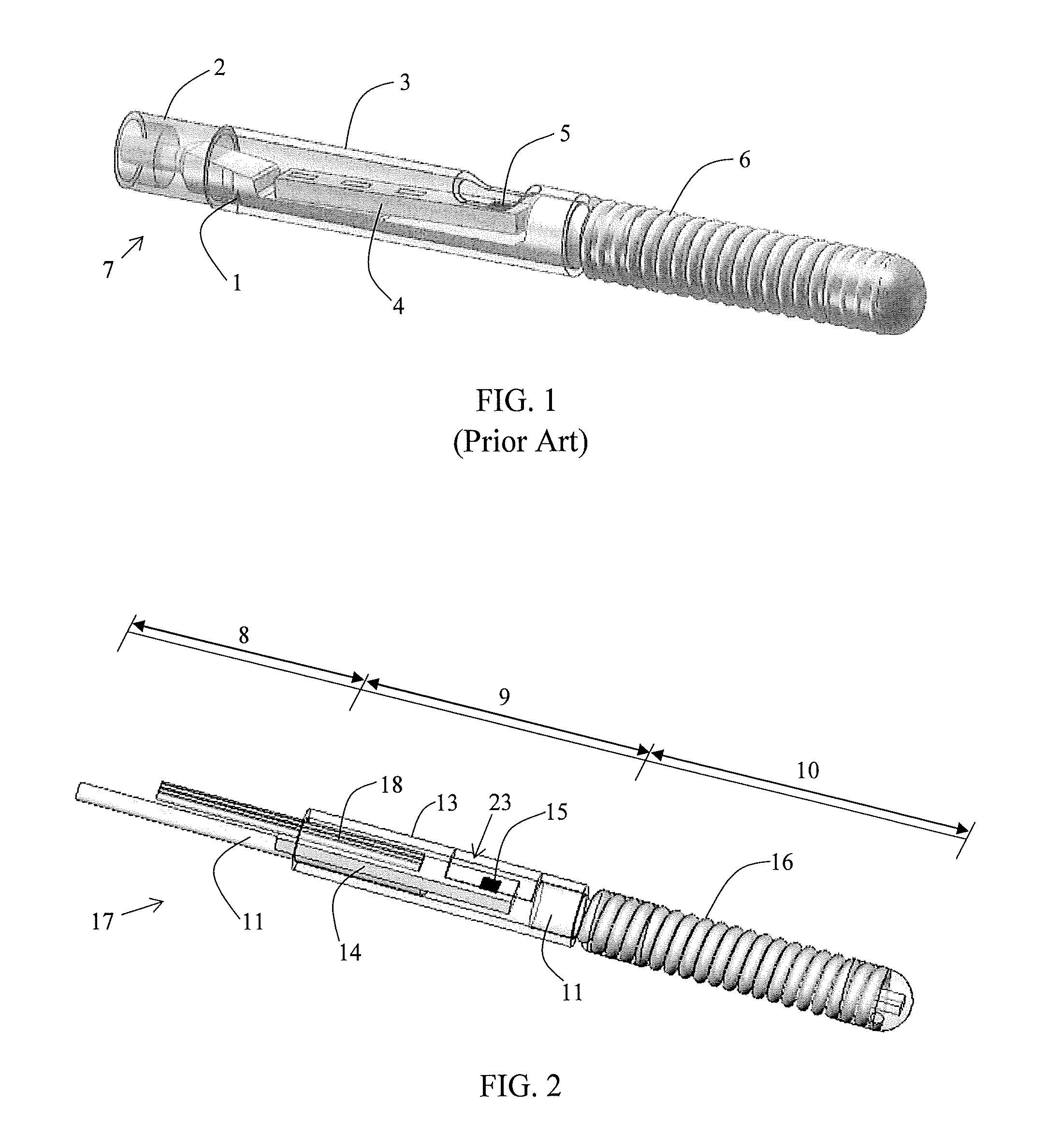
[0029]FIG. 1 illustrates a sensor guide wire 7 according to the prior art. The sensor guide wire 7 comprises a core wire 1, a hollow tube 2, a hollow jacket 3, a sensor element 4 with a sensor portion 5, and a coil 6. The core wire 1 is at least partly disposed inside the hollow tube 2 and extends through the jacket 3 and into the coil 6. The sensor element 4, comprising the sensor portion 5, is mounted on the core wire 1 within the jacket 3, and is connected to an electronic unit (not shown in the figure) via one or several electrical leads (not shown in the figure).

[0030]In FIG. 2 is disclosed, a sensor guide wire 17 for intravascular measurements of physiological variables in a living body, having a proximal region 8, a distal sensor region 9 and a tip region 10, according to the p...


PUM


Abstract

The present invention relates to a sensor guide wire (17) for intravascular measurements of physiological variables in a living body, having a proximal region (8), a distal sensor region (9) and a tip region (10). The sensor guide wire (17) further comprises a core wire member (11), a sensor element (14), which has a sensor portion (15), for measuring the physiological variable and to generate a sensor signal in response to said variable and a jacket (13), accommodating at least a part of said sensor element (14). The sensor portion (15), is sensitive to one or many of the physiological variables, pressure, temperature, and flow The core wire member (11) comprises two separate parts, a first core wire part (19) and a second core wire part (20), wherein a distal end (21) of said first core wire part (19) is attached to said jacket (13) proximally said sensor portion (15) and a proximal end (22) of said second core wire part (20) is attached to said jacket (13) distally to said sensor portion (15).

Description

FIELD OF THE INVENTION[0001]The present invention relates to a sensor guide wire for intravascular measurements of physiological variables in a living body, according to the preamble of the independent claim, and in particular to a sensor guide wire for intravascular pressure measurements having a divided core wire.BACKGROUND OF THE INVENTION[0002]In many medical procedures, various physiological conditions present within a body cavity need to be monitored. These physiological conditions are typically physical in nature—such as pressure, temperature, rate-of-fluid flow, and provide the physician or medical technician with critical information as to the status of a patient's condition.[0003]One device that is widely used to monitor conditions is the blood pressure transducer. A blood pressure transducer senses the magnitude of a patient's blood pressure, and converts it into a representative electrical signal that is transmitted to the exterior of the patient. For most applications i...

Claims


Application Information

Patent Timeline
Patent Type & Authority Applications(United States)
IPC IPC(8): A61M25/09A61B5/0205A61B5/027A61B5/0215A61B5/01
CPCA61B5/0215A61M25/09A61B5/6851
Inventor HILMERSSON, MATS
Owner ST JUDE MEDICAL COORDINATION CENT
Why Eureka
Try Eureka