Interface device and wiring board

a technology of interface device and wiring board, which is applied in the direction of electric digital data processing, instruments, etc., can solve the problems of increasing the number of terminals, naturally impossible to use usb 3.0, and the inability to solve the problem, so as to reduce the area of the board, flexiblely addressing a design chang

Inactive Publication Date: 2012-10-18
SHARP KK
View PDF25 Cites 9 Cited by
  • Summary
  • Abstract
  • Description
  • Claims
  • Application Information

AI Technical Summary

Benefits of technology

[0015]An object of the present invention is to provide an interface device capable of flexibly addressing a design change and the like in the case of mounting two serial communication interfaces such as PCI-e and USB 3.0 with standards different from each other, and reducing a board area, and a wiring board having the device mounted thereon.

Problems solved by technology

Therefore, when these two serial communication interfaces are attempted to be mounted on an information processing apparatus such as a PC, it needs to provide two types of the PIPE interfaces in total, each of which is provided for the PCI-e and the USB 3.0, thus posing a problem that the number of terminals increases and both the two types have enlarged board areas for accepting restrictions set to specifications. FIG. 4 shows a configuration of a conventional interface device equipped with the PCI-e interface and the USB 3.0 interface.
Further, in the case of assuming that a product is equipped with either one of the PCI-e and the USB 3.0, once wiring of the PIPE interface of the PCI-e is performed, it is naturally impossible to use the USB 3.0.
However, since no technological thought has been proposed that the PIPE interface is shared between the PCI-e and the USE 3.0 in conventional technologies so far, it is impossible to solve the problem as described above.

Method used


Image

  • Interface device and wiring board
  • Interface device and wiring board
  • Interface device and wiring board

Examples


Embodiment Construction

[0025]Hereinafter, description will be given for preferred embodiments according to an interface device and a wiring board having the device mounted thereon in the present invention with reference to accompanying drawings.

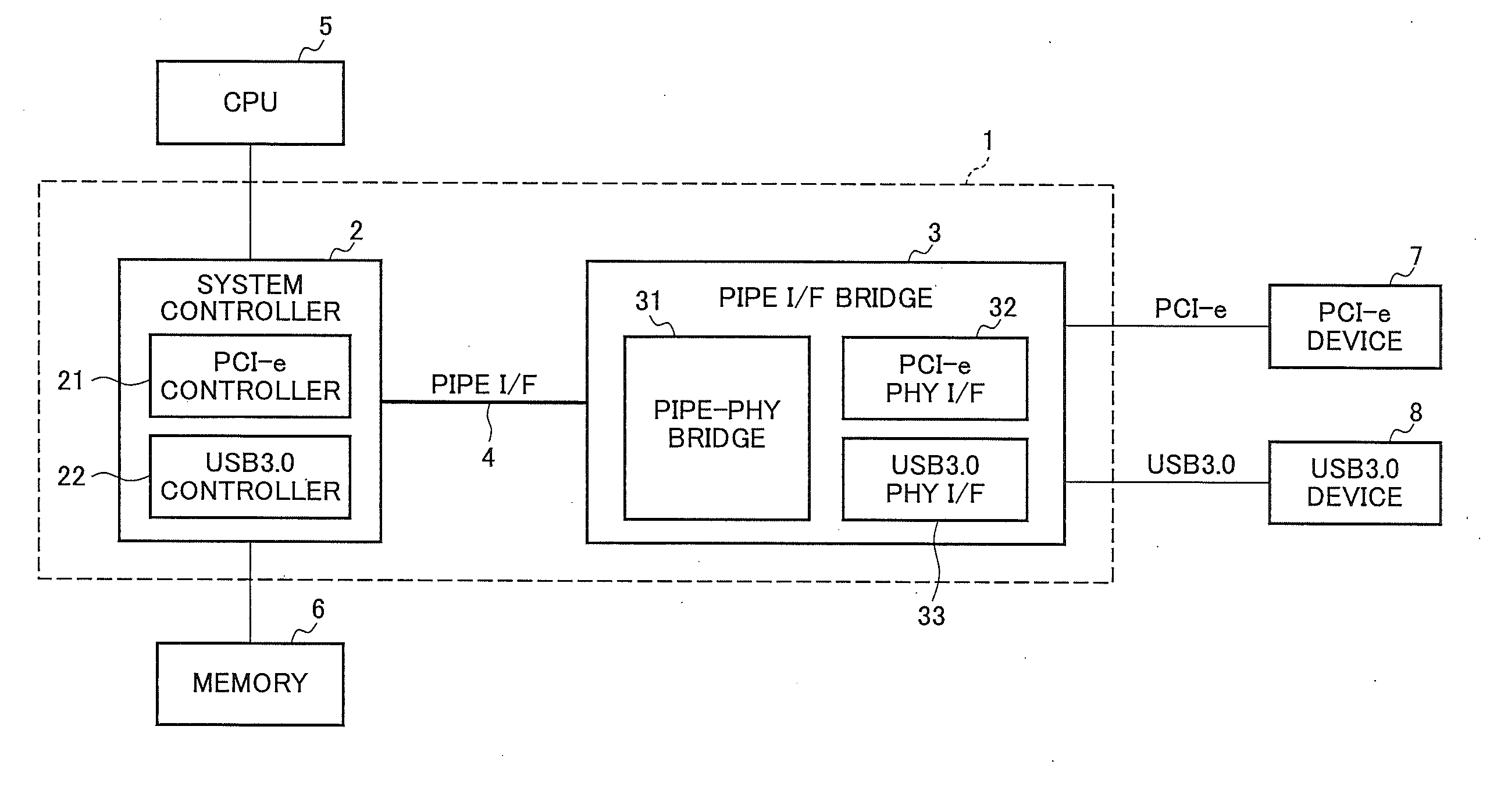
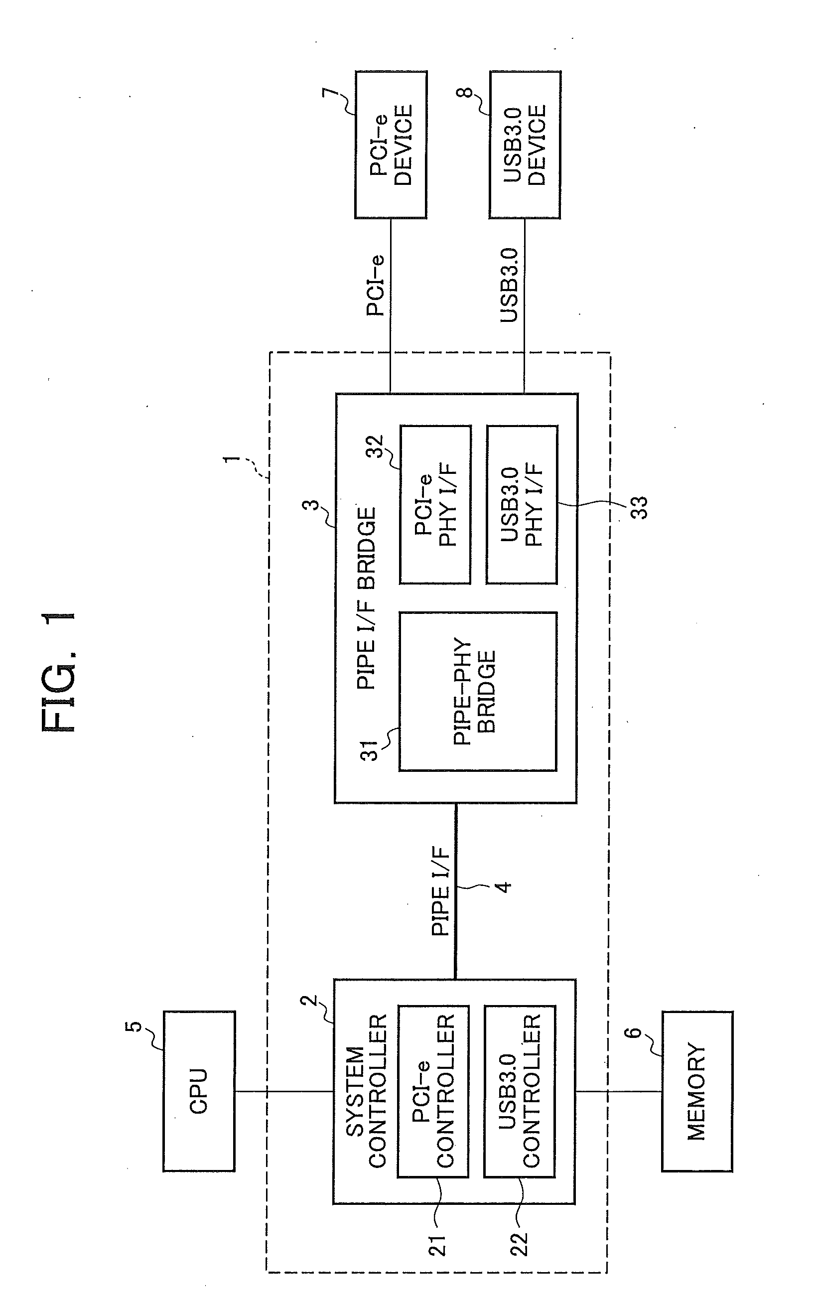
[0026]FIG. 1 is a block diagram showing a configuration example of an information processing apparatus provided with an interface device according to the present invention. This information processing apparatus is a common PC or the like comprised of an interface device 1, a CPU 5, a memory 6, a PCI-e device 7, and a USB 3.0 device 8. The interface device 1 is comprised of a system controller 2, a PIPE interface bridge (PIPE I / F bridge) 3, and a PIPE interface (PIPE I / F) 4.

[0027]The PIPE I / F bridge 3 is provided with a PIPE-PHY bridge 31, a PCI-e PHY interface (PCI-e PHY I / F) 32 and a USB 3.0 PHY interface (USB 3.0 PHY I / F) 33. The PCI-e device 7 is connected to the PCI-e PHY I / F 32, and the USB 3.0 device 8 is connected to the USB 3.0 PHY I / F 33. Note that, the PH...


PUM


Abstract

In the case of mounting two serial communication interfaces such as PCI-e and USB 3.0 with standards different from each other, it is allowed to flexibly address a design change and the like, and reduce a board area. An interface device is provided with a PCI-e PHY I / F, a USB 3.0 PHY I / F with equivalent specifications of a PIPE I / F to that of the PCI-e PHY I / F, and a system controller for controlling the PCI-e PHY I / F and the USB 3.0 PHY I / F. The interface device includes a PIPE I / F bridge in which the PCI-e PHY I / F and the USB 3.0 PHY I / F are provided, and the PIPE I / F bridge selectively switches connection of the PCI-e PHY I / F or the USB 3.0 PHY I / F with the system controller.

Description

CROSS-NOTING PARAGRAPH[0001]This non-provisional application claims priority under 35 U.S.C. §119 (a) on Patent Application No. 2011-091696 filed in JAPAN on Apr. 18, 2011, the entire contents of which are hereby incorporated herein by reference.FIELD OF THE INVENTION[0002]The present invention relates to an interface device and a wiring board, and more particularly, to an interface device of PCI-Express, USB 3.0 and the like allowing high-speed serial transfer, and a wiring board having the device mounted thereon.BACKGROUND OF THE INVENTION[0003]Recently, in a field of an information processing apparatus including a personal computer (PC), an interface device employing a high-speed serial transmission system has been commercialized such as PCI-Express (Peripheral Component Interconnect Express, hereinafter, referred to as PCI-e) and USB (Universal Serial Bus) 3.0. This PCI-e employs not a conventional parallel transmission system but a serial transmission system, in which one seria...

Claims


Application Information

Patent Timeline
Patent Type & Authority Applications(United States)
IPC IPC(8): G06F13/42
CPCG06F13/40G06F13/4059G06F2213/0026G06F2213/0042G06F13/42G06F13/14
Inventor JONO, MASAYUKINAKAJIMA, TOMOKI
Owner SHARP KK
Why Eureka
Try Eureka