Microfluidic cartridge with parallel pneumatic interface plate

Active Publication Date: 2012-10-25
KONINKLJIJKE PHILIPS NV
View PDF4 Cites 51 Cited by
  • Summary
  • Abstract
  • Description
  • Claims
  • Application Information

AI Technical Summary

Benefits of technology

[0018]It may be seen as an essential characteristic of the provided microfluidic cartridge to realize the actuating of fluids in the cartridge by a pneumatic instrument. The facts, that the pneumatic driving makes use of a flexible cartridge membrane and that the pneumatic chambers underneath the membrane are reversibly assembled are important. This means, that the separation plane between the cartridge and the pneumatic instrument crosses the pneumatic chambers.
[0019]In other words when the cartridge is removed the pneumatic supply channels, pneumatic channels and pneumatic chambers are open. The chambers underneath the actuated membrane are formed by the combination of the cartridge and the interface plate on the instrument. When the cartridge is lifted up the pressure may not be transferred anymore to the membrane, in contrast to tubing, which is not used for the actuation of the membrane according to the present invention and which tubing is fixed mechanically.
[0020]The microfluidic cartridge may be used in combination with a pneumatic instrument, that contains supply channels for the pneumatic driving and that contains a substantially flat interface plate towards the microfluidic cartridge that contains the fluid channels. The fluid channels are confined by a flexible layer which may be actuated once the cartridge is put on the instrument. By moving the flexible membrane up and down a volume is displaced inside the cartridge and the membrane can close channels to provide for a valve function within fluid channel.
[0021]The stroke of the membrane deflection is based on the height between the position of the membrane when touching the pneumatic interface plate of the pneumatic instrument

Problems solved by technology

An issue in these micro fluidic systems is the manipulation of the fluids from and to the different reaction chambers, for which micro actuators such as pumps and valves are needed.
The latter is a cost-effective solution but does not allow for flow reversal, the flow rate is limited and not constant with distance and most importantly depending on the viscosity

Method used


Image

  • Microfluidic cartridge with parallel pneumatic interface plate
  • Microfluidic cartridge with parallel pneumatic interface plate
  • Microfluidic cartridge with parallel pneumatic interface plate

Examples


Embodiment Construction

[0087]Similar or relating components in the several figures are provided with the same reference numerals. The view in the figure is schematic and not fully scaled.

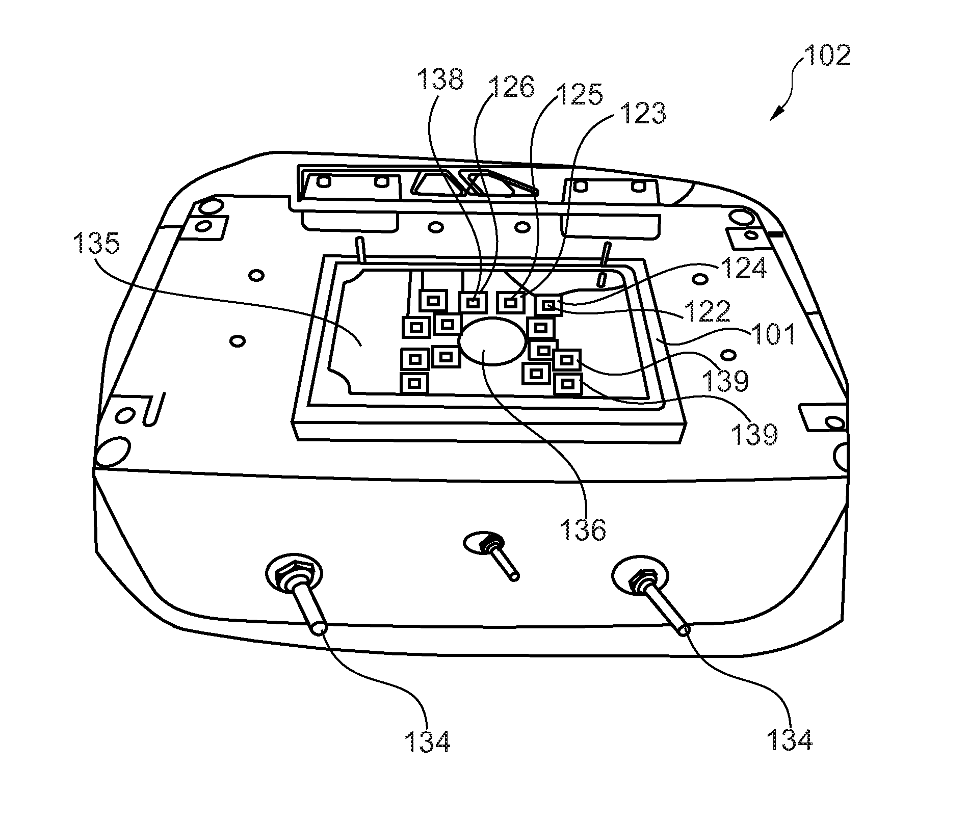
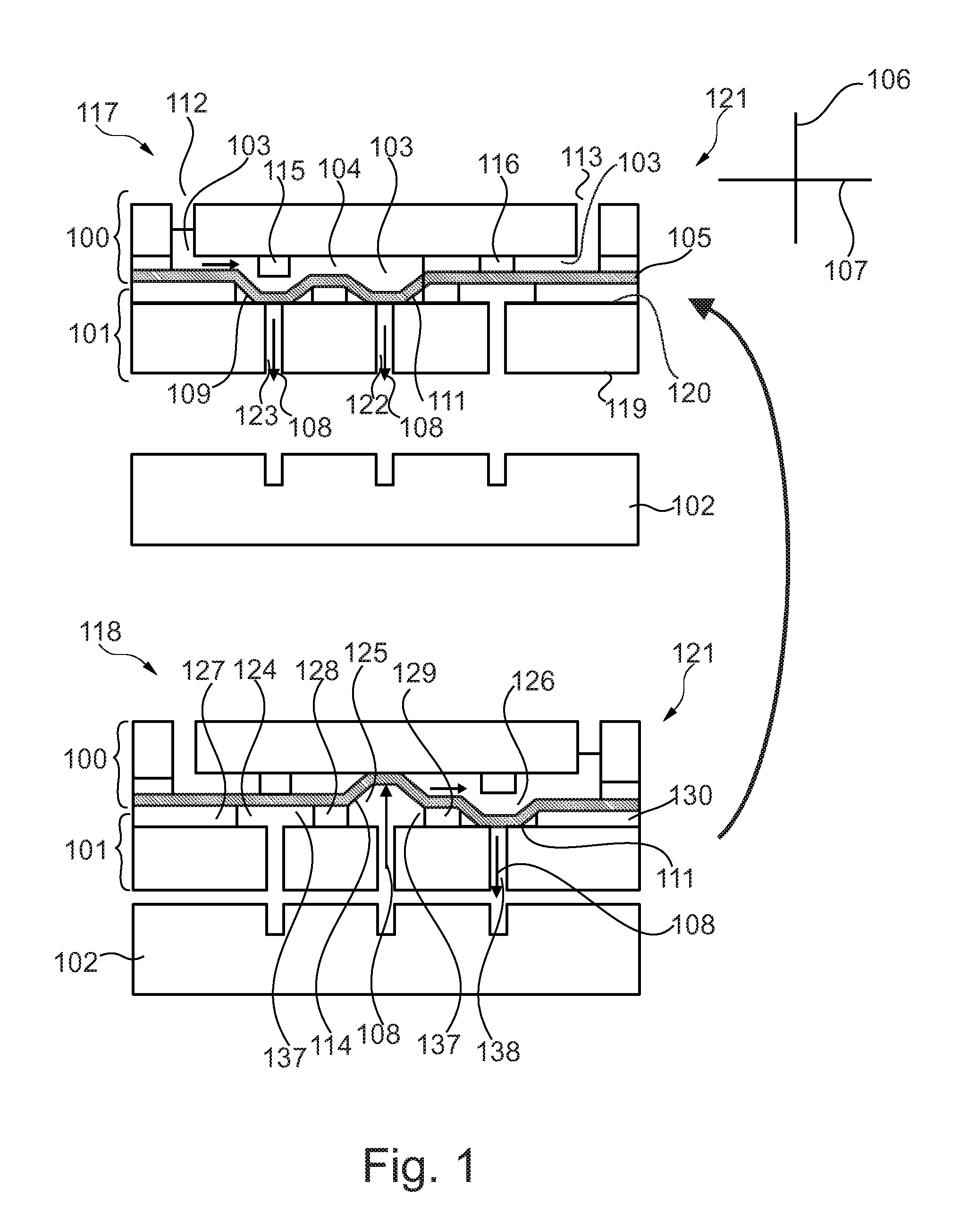
[0088]FIG. 1 shows in the upper part a system 121 for fluid actuation inside a microfluidic cartridge 100 in a first state wherein the lower part of FIG. 1 shows such a system 121 in a second state, in which the contained fluid 104 inside the cartridge has been transported. Both shown systems 121, the upper and the lower one, consist of the same elements.

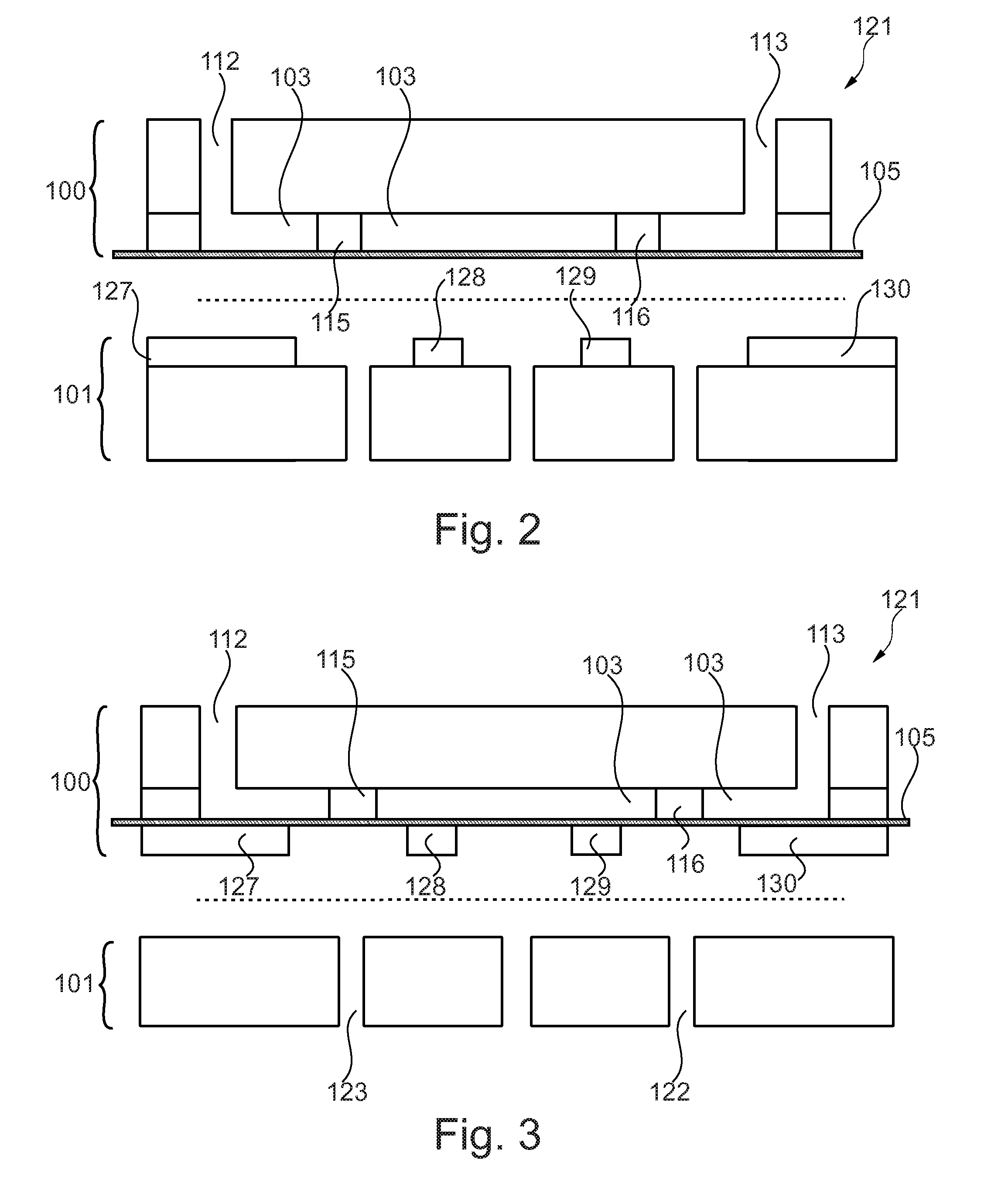
[0089]FIG. 1 shows a microfluidic cartridge 100 for being inserted in the parallel pneumatic interface plate 101 of a pneumatic instrument wherein the cartridge comprises a three-dimensional fluid channel 103 in which a fluid 104 is to be transported. Furthermore the cartridge comprises a flexible membrane 105 wherein the flexible membrane spans a plane. The plane spans along the direction 107. Furthermore the flexible membrane builds an outer surface of the cartridge whe...


PUM


Abstract

A microfluidic cartridge for placement onto a parallel pneumatic interface plate of a pneumatic instrument is provided. The cartridge includes a three dimensional fluid channel, in which a fluid is to be transported, a flexible membrane that spans a plane and is part of an outer surface of the cartridge. The three dimensional fluid channel is spatially defined in three dimensions by internal walls of the cartridge and by the flexible membrane. The flexible membrane is in a ground state, when no pressure or vacuum is applied to the flexible membrane. However, the flexible membrane is pneumatically deflectable from the ground state perpendicular to the plane of the flexible membrane in two directions when the cartridge is placed onto the parallel pneumatic interface plate.

Description

FIELD OF THE INVENTION[0001]The invention relates to fluid actuation in microfluidic cartridges. The invention especially relates to a microfluidic cartridge for being inserted in a parallel pneumatic interface plate of a pneumatic instrument, an interface plate for interfacing with a microfluidic cartridge and between a pneumatic instrument, a system for fluid actuation inside a micro fluidic cartridge comprising such a cartridge and such an interface plate and relates to a pneumatic instrument.BACKGROUND OF THE INVENTION[0002]Biosensors are used for the detection of molecules in biological samples, for instance proteins or DNA for diagnostic applications. It is also desired to detect drugs, therapeutic or abuse, in blood, urine or saliva. Such tests are developed to be used in many different settings and surroundings, e.g. at the point of care for medical applications, or at any desired place for drugs of abuse, e.g. at the roadside. In all cases a robust, reliable and sensitive d...

Claims


Application Information

Patent Timeline
IPC IPC(8): F04F1/00
CPCB01L3/502715F04B43/06B01L3/502738B01L2300/0809B01L2300/0874B01L2300/123B01L2300/1805B01L2400/0481B01L2400/0487B01L2400/0638F04B19/006F04B43/043F16K99/0001F16K99/0015F16K99/0059F16K2099/0084B01L3/50273Y10T137/85978B01L3/00F04B19/00F16K99/00
Inventor WIMBERGER-FRIEDL, REINHOLDPENTERMAN, ROELVAN AMERONGEN, HENDRIK HALLINGLORING, THEODORUS ANTONIUS JOHANNESVAN UDEN, MARTIJN JOCHEM
Owner KONINKLJIJKE PHILIPS NV
Why Eureka
Try Eureka