Ribbon capable of enhancing cutting precision

a technology of cutting precision and ribbon, which is applied in the field of ribbon, can solve the problems of the length of the print medium with the printed image not meeting the length of the physical image, and the error in calculating the length of the print medium moved, so as to enhance the cutting precision of the thermal sublimation printer, avoid fracturing the surface of the print medium, and keep print quality. good

a technology of cutting precision and ribbon, which is applied in the field of ribbon, can solve the problems of the length of the print medium with the printed image not meeting the length of the physical image, and the error in calculating the length of the print medium moved, so as to enhance the cutting precision of the thermal sublimation printer, avoid fracturing the surface of the print medium, and keep print quality. good

US20120268545A1Inactive Publication Date: 2012-10-25HI TOUCH IMAGING TECH CO LTD

Image

  • Ribbon capable of enhancing cutting precision
  • Ribbon capable of enhancing cutting precision
  • Ribbon capable of enhancing cutting precision

Examples


Embodiment Construction

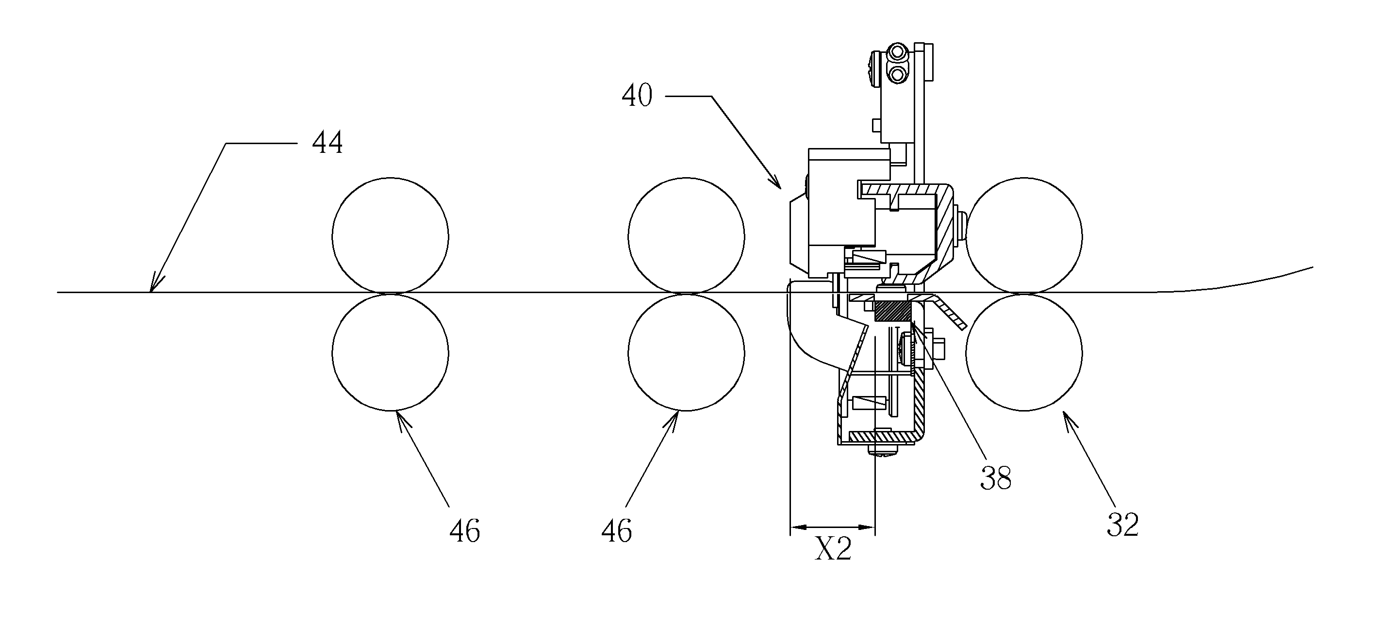
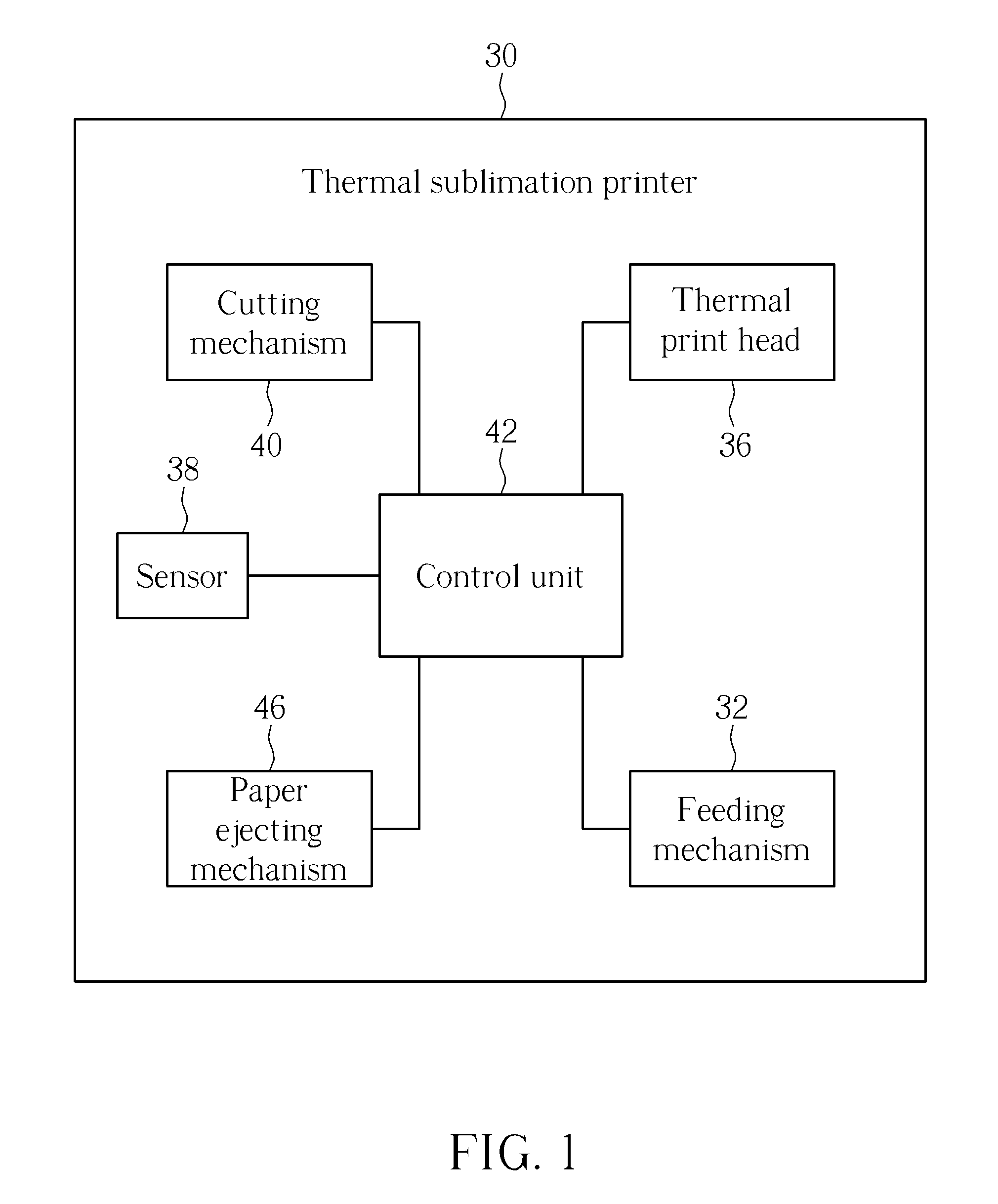
[0022]Please refer to FIG. 1. FIG. 1 is a functional block diagram illustrating a ribbon 34 adapted to a thermal sublimation printer 30 according to a preferred embodiment of the present invention. As shown in FIG. 1, the thermal sublimation printer 30 includes a feeding mechanism 32, a thermal print head 36, a sensor 38, a cutting mechanism 40 and a control unit 42. The feeding mechanism 32 is used for moving a print medium 44 such as a sheet of paper, and the thermal print head 36 is used for transferring dyes on the ribbon 34 onto the print medium 44. In this embodiment, the feeding mechanism 32 can be preferably a rubber roller transmission system for avoiding from fracturing the surface of print medium 44, so as to keep print quality.

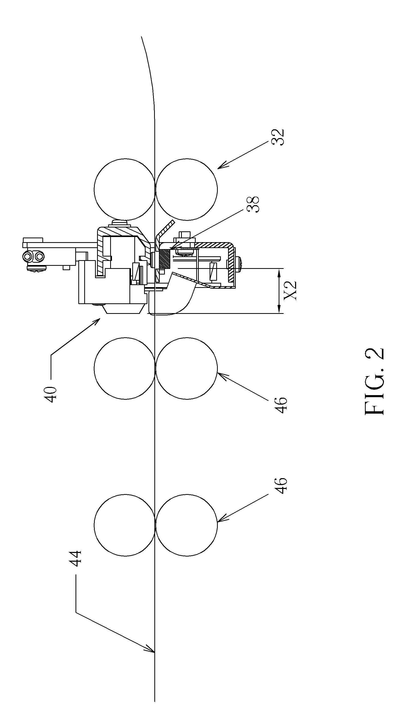
[0023]Please refer to FIG. 1 to FIG. 4. FIG. 2 is a schematic diagram of the cutting mechanism 40 according to the preferred embodiment of the present invention. FIG. 3 is a partially schematic diagram of the ribbon 34 according to the preferred em...


PUM

PropertyMeasurementUnit
lengthaaaaaaaaaa
dark-coloraaaaaaaaaa
distanceaaaaaaaaaa

Abstract

A ribbon includes at least one dye region, at least one separating region and at least one recognition dye region. Each of the dye regions includes a plurality of dye zones. The separating region is formed on a side of the dye region for separating different dye regions. The recognition dye region is formed on the separating region or formed within a range covered by the corresponding dye region. A thermal print head of a thermal sublimation printer transfers the dye region and the recognition dye region of the ribbon onto a print medium, so as to form an image area and a recognition mark on the print medium, correspondingly. A cutting mechanism of the thermal sublimation printer is used for cutting the print medium when a sensor of the thermal sublimation printer senses the recognition mark.

Description

BACKGROUND OF THE INVENTION[0001]1. Field of the Invention[0002]The present invention relates to a ribbon, and more particularly, to a ribbon adapted to a thermal sublimation printer for enhancing cutting precision.[0003]2. Description of the Prior Art[0004]A conventional thermal sublimation printer with duplex printing function utilizes a motor to drive a feeding mechanism with a rubber roller, so as to move a print medium to a position where a thermal print head is located. Afterwards, the thermal print head transfers dyes on a ribbon onto the print medium. After completing dye transferring, the motor continues to drive the feeding mechanism for moving the print medium to a position where a cutting mechanism is located. The cutting mechanism is used for cutting the print medium, so as to make a length of the print medium with a printed image be identical to that of a physical image. Consequently, and it is easy and convenient for a user to take the said cutting printed medium.[000...

Claims


Application Information

Patent Timeline
25 Oct 2012
Publication
US20120268545A1
IPC
B41J2/325
CPC
B41J11/663; B41M5/00; B41J31/02
Inventors
CHEN, CHIEN-JU; HUANG, YAO-HSIEN