Liquid Crystal Display Device

a liquid crystal display and display screen technology, applied in non-linear optics, instruments, optics, etc., can solve problems such as light leakage, error in driving a screen, and limit the bezel area of the display screen, so as to prevent the damage prevent the flexure of the liquid crystal panel and light leakage, and increase the display quality

Active Publication Date: 2012-10-25
LG DISPLAY CO LTD
View PDF12 Cites 26 Cited by
  • Summary
  • Abstract
  • Description
  • Claims
  • Application Information

AI Technical Summary

Benefits of technology

[0019]An aspect of the present invention is directed to provide an LCD device which can prevent the damage of a liquid crystal panel.
[0020]Another aspect of the present invention is directed to provide an LCD device which prevents the flexure of a liquid crystal panel and light leakage, leading to the increase in display quality.
[0021]Another aspect of the present invention is directed to provide a borderless LCD device which has the enhanced ability to remove static electricity.
[0022]Another aspect of the present invention is directed to provide a borderless LCD device which has the reduced thickness and the enhanced sense of beauty in a front surface.

Problems solved by technology

In LCD devices of the related art, since an area for sustaining the weight of a liquid crystal panel is required, there is a limitation in reducing the bezel area.
Due to this reason, liquid crystal molecules are not smoothly aligned, causing light leakage.
Also, since there is no path for discharging the static electricity, an error occurs in driving a screen.

Method used


Image

  • Liquid Crystal Display Device
  • Liquid Crystal Display Device
  • Liquid Crystal Display Device

Examples


first embodiment

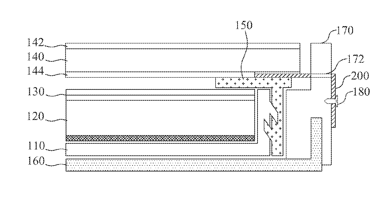
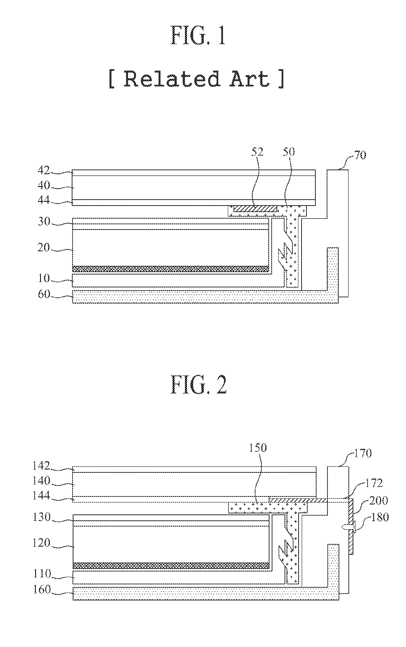
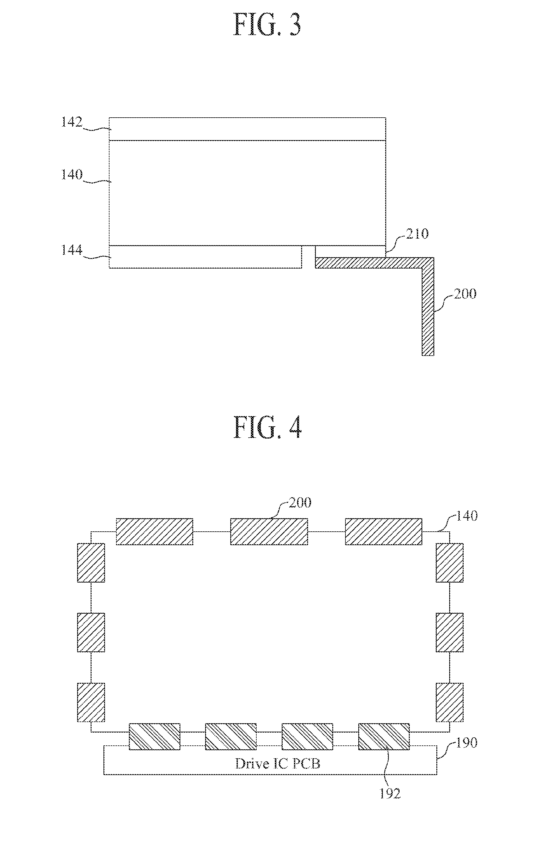
[0034]FIGS. 2 and 3 are views illustrating an LCD device according to the present invention.

[0035]Referring to FIGS. 2 and 3, the LCD device according to the first embodiment of the present invention includes a cover bottom 110, a liquid crystal panel 140, a guide panel 150, a set back cover 160, a side cover 170, a conductive flexible film 200, and an adhesive member 210.

[0036]Moreover, the LCD device according to the first embodiment of the present invention includes a backlight unit, and a driving circuit part for driving the liquid crystal panel 140 and a light source.

[0037]The liquid crystal panel 140 includes an upper substrate (color filter array substrate) and a lower substrate (TFT array substrate) that are coupled about a liquid crystal for adjusting a light transmittance.

[0038]A plurality of gate lines and data lines are formed to intersect each other, at the lower substrate. A plurality of pixels are defined by the intersection of the gate lines and data lines. A Thin Fi...

second embodiment

[0085]Referring to FIGS. 5 and 6, the LCD device according to the present invention includes a cover bottom 110, a liquid crystal panel 140, a guide panel 150, a set back cover 160, a side cover 170, a conductive flexible film 200, an adhesive member 210, and an electrostatic discharge (ESD) pad 220.

[0086]The guide panel 150 includes a side wall and a support part for supporting the liquid crystal panel 140. The support part is disposed on a side wall of the cover bottom 110.

[0087]The support part of the guide panel 150 is formed to surround an edge portion of the liquid crystal panel 140. The side wall of the guide panel 150 is coupled and fixed to the side wall of the cover bottom 110.

[0088]A conductive flexible film 200 is disposed on the support part of the guide panel 150, and adhered to a rear surface of the liquid crystal panel 140 by the adhesive member 210.

[0089]The conductive flexible film 200 includes a disposing part and a fixing part. The fixing part is bent vertically ...


PUM

PropertyMeasurementUnit
thicknessaaaaaaaaaa
heightaaaaaaaaaa
flexibleaaaaaaaaaa

Abstract

Discussed is an LCD device. The LCD device includes a guide panel, a side cover, a flexible film, and an adhesive member. The guide panel includes a side wall and a support part formed to surround a lower edge of a liquid crystal panel, and supports the liquid crystal panel. The side cover is formed to surround a side surface of the liquid crystal panel and a side surface of the guide panel, and a hole is formed at a portion of the liquid crystal panel having a certain height. The flexible film is disposed between the support part of the guide panel and the liquid crystal panel. The adhesive member adheres a bottom of the liquid crystal panel to the flexible film.

Description

CROSS-REFERENCE TO RELATED APPLICATIONS[0001]This application claims the priority benefit of the Korean Patent Application No. 10-2011-0037359 filed on Apr. 21, 2011, which is hereby incorporated by reference as if fully set forth herein.BACKGROUND[0002]1. Field of the Invention[0003]The present invention relates to a display device, and more particularly, to a Liquid Crystal Display (LCD) device which prevents light leakage and thus has the enhanced display quality and the enhanced ability to remove static electricity.[0004]2. Discussion of the Related Art[0005]Various flat panel display devices that can decrease a weight and a volume corresponding to the limitations of Cathode Ray Tubes (CRTs) are being developed, and the demand of the flat panel display devices is increasing.[0006]Liquid Crystal Display (LCD) devices, Plasma Display Panels (PDPs), Field Emission Display (FED) devices, and Light Emitting Diode (LED) display devices have been developed as flat panel display devices...

Claims


Application Information

Patent Timeline
Patent Type & Authority Applications(United States)
IPC IPC(8): G02F1/1333
CPCG02F1/133308G02F1/13452G02F2202/28G02F2202/22G02F2001/133317G02F1/133317G02F1/1333G02F1/1335G02F1/1337G02F1/1345G02F1/133334
Inventor LEE, YOUNGNAMJO, JUNYOUNGKIM, YOUNGOK
Owner LG DISPLAY CO LTD
Why Eureka
Try Eureka