Displacement-induction neutral wall air terminal unit

a technology of displacement unit, which is applied in the field of displacement-induction neutral wall air terminal unit, can solve the problems of troublesome heating system placement, inability to place heating systems in the same location, and inability to function as displacement terminal units, so as to increase the overall heating capacity of the unit

Active Publication Date: 2012-10-25
SCHWAB VOLLHAVER LUBRATT
View PDF26 Cites 13 Cited by
  • Summary
  • Abstract
  • Description
  • Claims
  • Application Information

AI Technical Summary

Benefits of technology

[0004]An induction-displacement neutral wall air terminal unit is disclosed. The disclosed unit has a housing defining a supply airflow path extending between a ventilation air inlet and a supply air outlet, a return airflow path extending between a return air inlet and the supply airflow path, and a neutral wall heating airflow path extending between an inlet and an outlet. The heating airflow path is separated from the supply and return airflow paths by at least one interior wall. The unit also includes a plurality of induction-type nozzles located within the supply airflow path. The induction-type nozzles are constructed and arranged to deliver a ventilation air flow stream into the supply air flow path and to induce a return air flow stream through the return air flow path that mixes with the ventilation air flow stream to form a supply air flow stream. Additionally, a heating element is disposed and heats air within the ne

Problems solved by technology

However, in doing so, the induction-displacement unit can no longer function as a displacement terminal unit due to the fact that the delivered air starts rising as soon as it leaves the unit instead of pooling across the floor.
However, as the induction-displacement units are placed

Method used


Image

  • Displacement-induction neutral wall air terminal unit
  • Displacement-induction neutral wall air terminal unit
  • Displacement-induction neutral wall air terminal unit

Examples


example performance

Data:

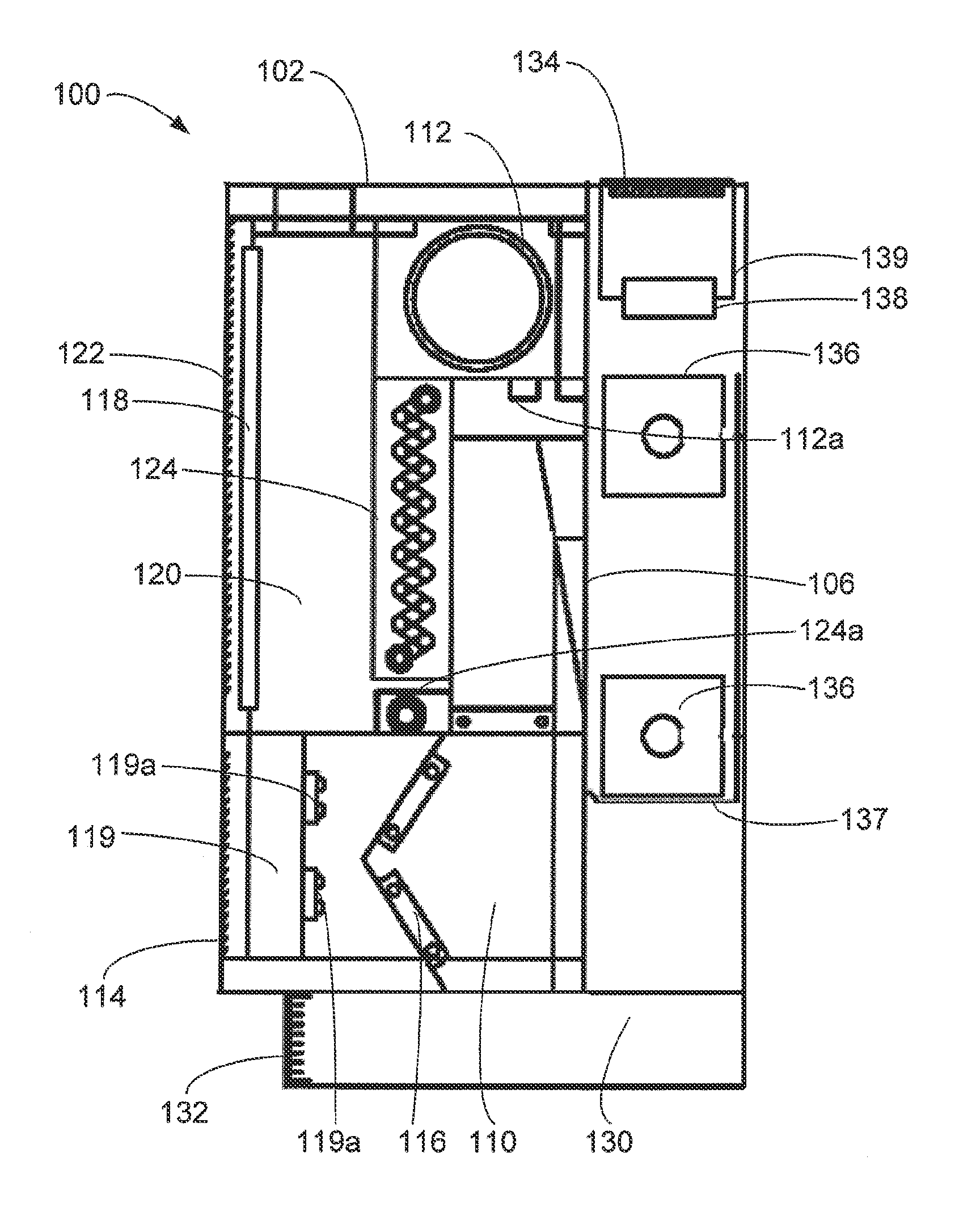
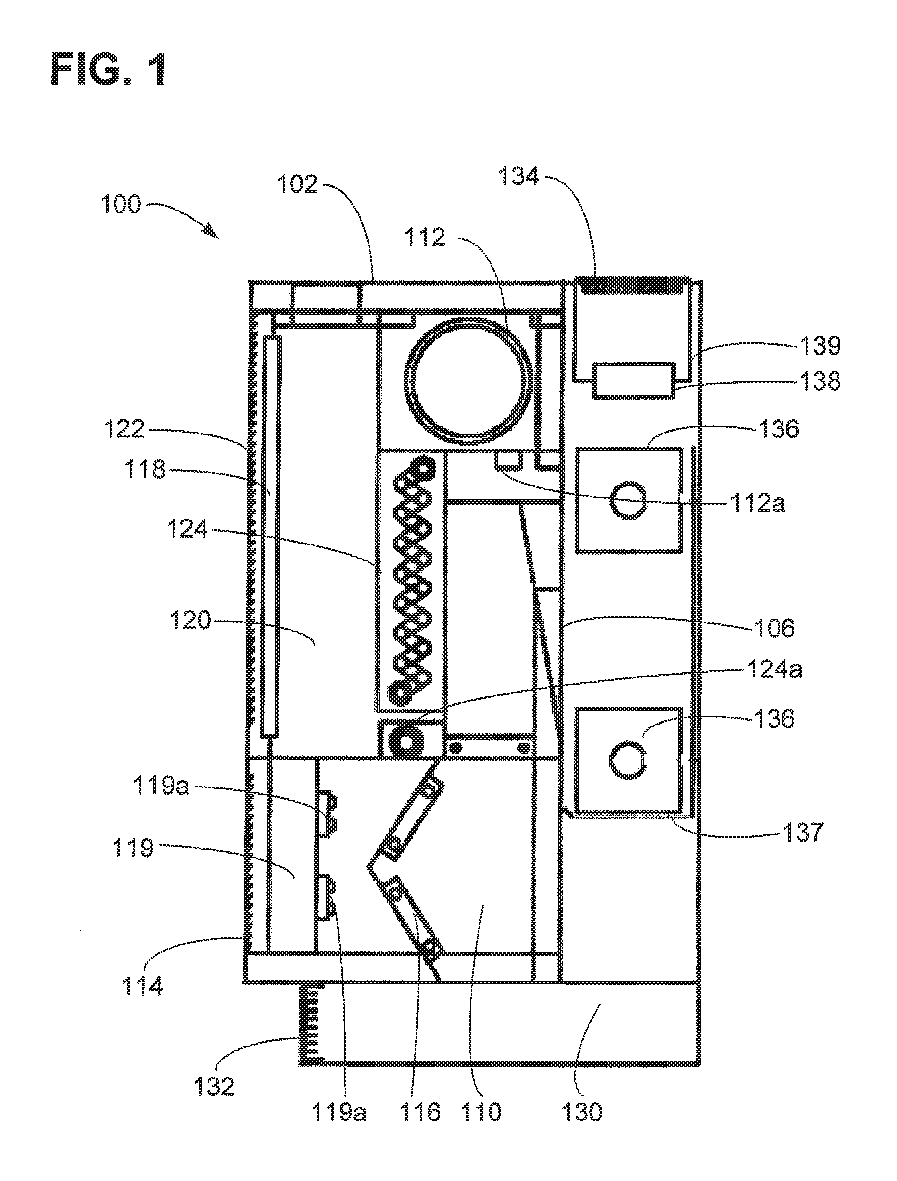
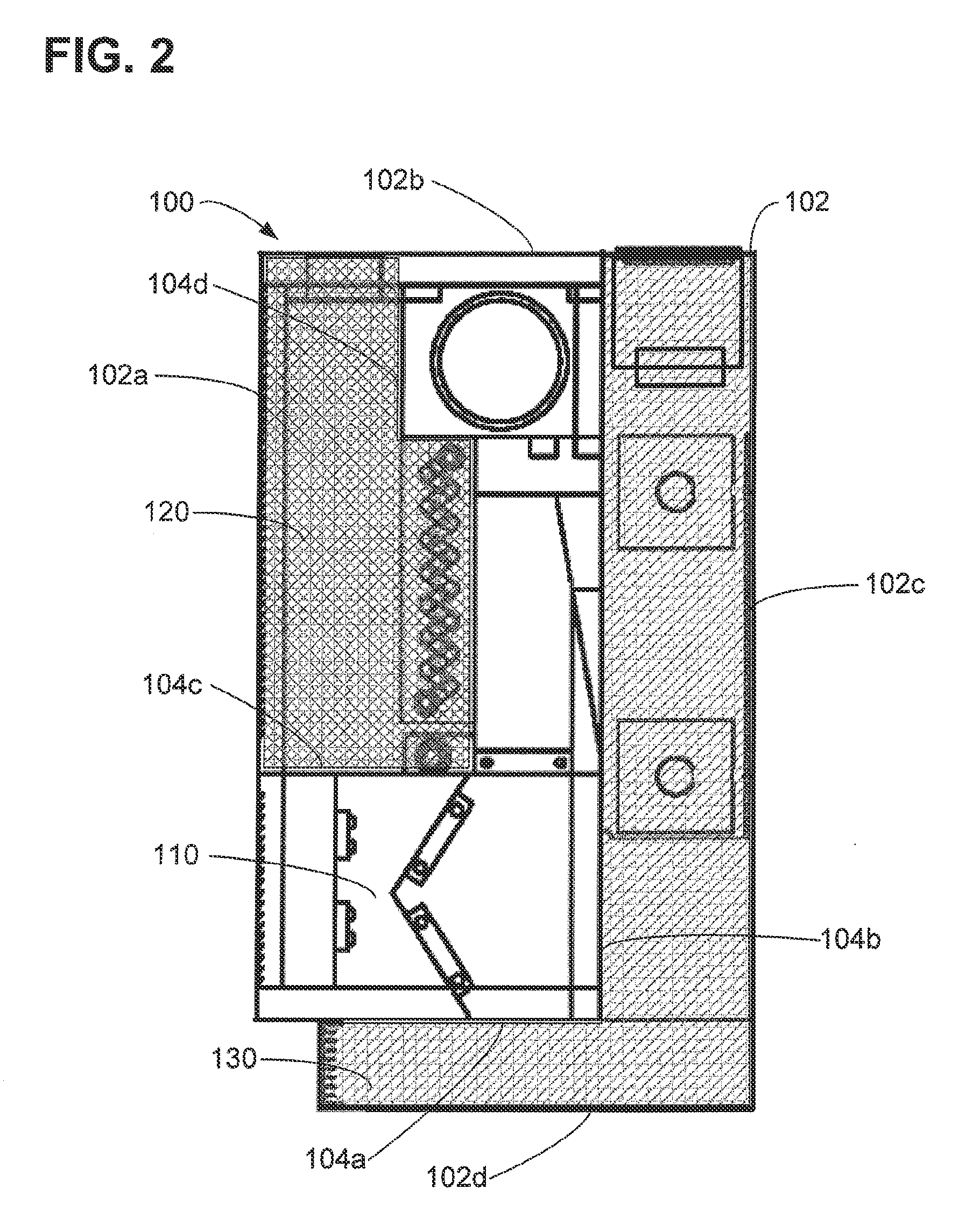
[0035]For the purpose of providing an example configuration of unit 100, and anticipated performance, table 1 is provided below.

TABLE 1Nominal Unit Length72inchesVentilation airflow rate110cfmReturn airflow rate (air induced into unit by220cfmventilation airflow stream)Supply airflow rate330cfmReturn air coil cooling capacity1,700 btuh (sensiblecooling to 61° F.)Ventilation airflow stream cooling capacity3,025 btuh (at 53° F.supply temperature)Heating capacity through heating airflow path9,300btuh(average water temperature 170° F. without fan)Heating capacity through heating airflow path10,000btuh(average water temperature 110 with fan)Noise Levels26.5 (exceeds ANSI / ASA StandardS12.60 of NC 27)

[0036]As can be appreciated, Table 1 shows that unit 100 is capable of providing simultaneous heating through the heating airflow path and displacement air to the space at a temperature independent of the heating airflow path.


PUM


Abstract

An induction-displacement neutral wall air terminal unit includes a housing defining a supply airflow path, a connected return airflow path, and a heating airflow path separated from the supply and return airflow paths by at least one interior wall. The unit also includes a plurality of induction-type nozzles located within the supply airflow path, that are deliver a ventilation air flow stream into the supply air flow path. The nozzles induce a return air flow stream through the return air flow path that mixes with the ventilation air flow stream to form a supply air flow stream delivered to a supply air outlet. A heating element is disposed within the heating airflow path to heat air within the heating air flow path. A plurality of fans may be placed within the heating airflow path to increase the overall heating capacity of the unit.

Description

TECHNICAL FIELD [0001]This disclosure relates to heating, ventilation, and air-conditioning (HVAC) systems, and particularly to air terminal units configured to simultaneously provide heating and displacement ventilation to a space.BACKGROUND [0002]Displacement ventilation systems are in wide spread use in the HVAC industry. One particular application for such systems is in school buildings. Typically, a number of displacement air terminal devices will be located along a perimeter wall of a classroom space and are configured to deliver ventilation air to the space. The ventilation air is generally several degrees below the space set point temperature to ensure that the ventilation air effectively pools across the floor of the space. Due to the heat generated by the occupants and equipment in the space, the ventilation air is naturally drawn up by convection which ensures fresh air is continually delivered to the breathing zone of the occupants. The heated air continues to rise to th...

Claims


Application Information

Patent Timeline
IPC IPC(8): F24F7/00F24F1/0068
CPCF24F1/0007F24F1/01F24F2001/004F24F2221/34F24F2221/54F24F1/0033F24D3/02F24D19/0087F24D19/1003F24D19/1009F24D1/00Y02B30/17F24F1/005F24D10/003Y02B30/00F24F1/0068
Inventor MCCARTY, DANIEL P.
Owner SCHWAB VOLLHAVER LUBRATT
Why Eureka
Try Eureka