Definition of wakeup bus messages for partial networking

a technology of partial networking and wake-up bus, which is applied in the field of bus system, can solve the problems of unnecessarily using power, consuming energy, and unwanted wake-up events

Inactive Publication Date: 2012-10-25
NXP BV
View PDF3 Cites 26 Cited by
  • Summary
  • Abstract
  • Description
  • Claims
  • Application Information

AI Technical Summary

Benefits of technology

[0044]Accordingly, a bus node or a pattern detector comprising the above technical features is able to decode such bus message information, i.e. bus messages, in a more reliable manner. In particular, the bus node or pattern detector is able to compare bus message signals encoded respectively with a pre-stored bit sequence and the series of relative length information for the sub-patterns, detected in decoding of the bus message information, with a respectively predefined series, if the two are the same, to wake up the bus node, i.e. the part of the bus node, e.g. the microcontroller unit, the bus protocol controller or even the transceiver, that is in the stand by or sleep state.

Problems solved by technology

A disadvantage is the fact that, for individual stations to be selectively woken, wake-up bus messages have to be decoded, for which purpose the part of the bus node that is on standby at the relevant point in time has to have an accurate timer mechanism, which consumes energy.
This leads still to unwanted wake-up events, which can use power unnecessarily.
A further problem with known wake-up patterns is that the defined wakeup patterns do not allow for addressing different wakeup-groups and there is no definition of IDs and priorities to be used.

Method used


Image

  • Definition of wakeup bus messages for partial networking
  • Definition of wakeup bus messages for partial networking
  • Definition of wakeup bus messages for partial networking

Examples


Embodiment Construction

[0049]In the following by way of example the herein disclosed method for encoding particular bus messages and the improved pattern detector are described with respect to a controller area network (CAN). However, it will be appreciated that the invention is not limited to such a network but may be applied to a local interconnect network (LIN) or FlexRay network or the like as well.

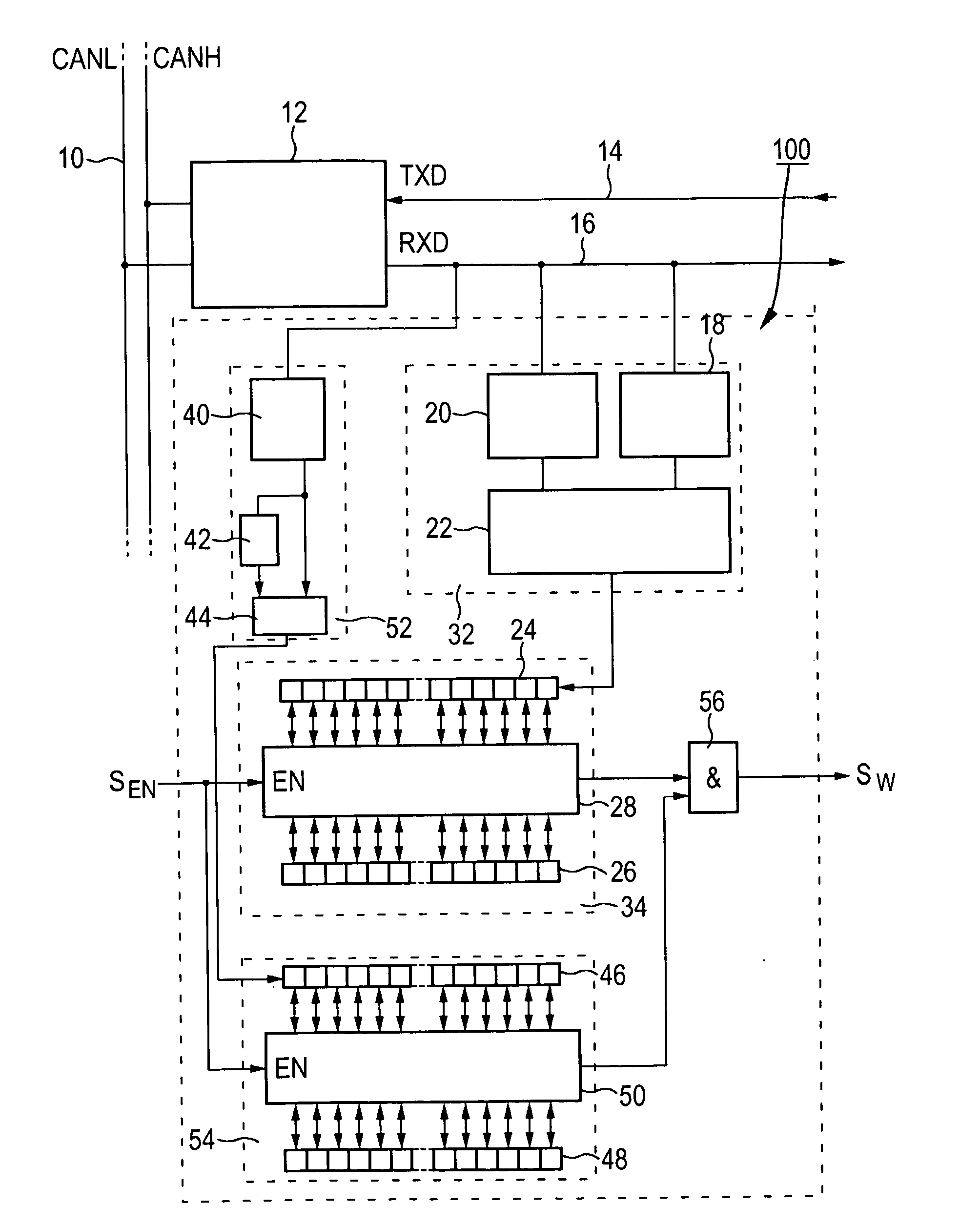
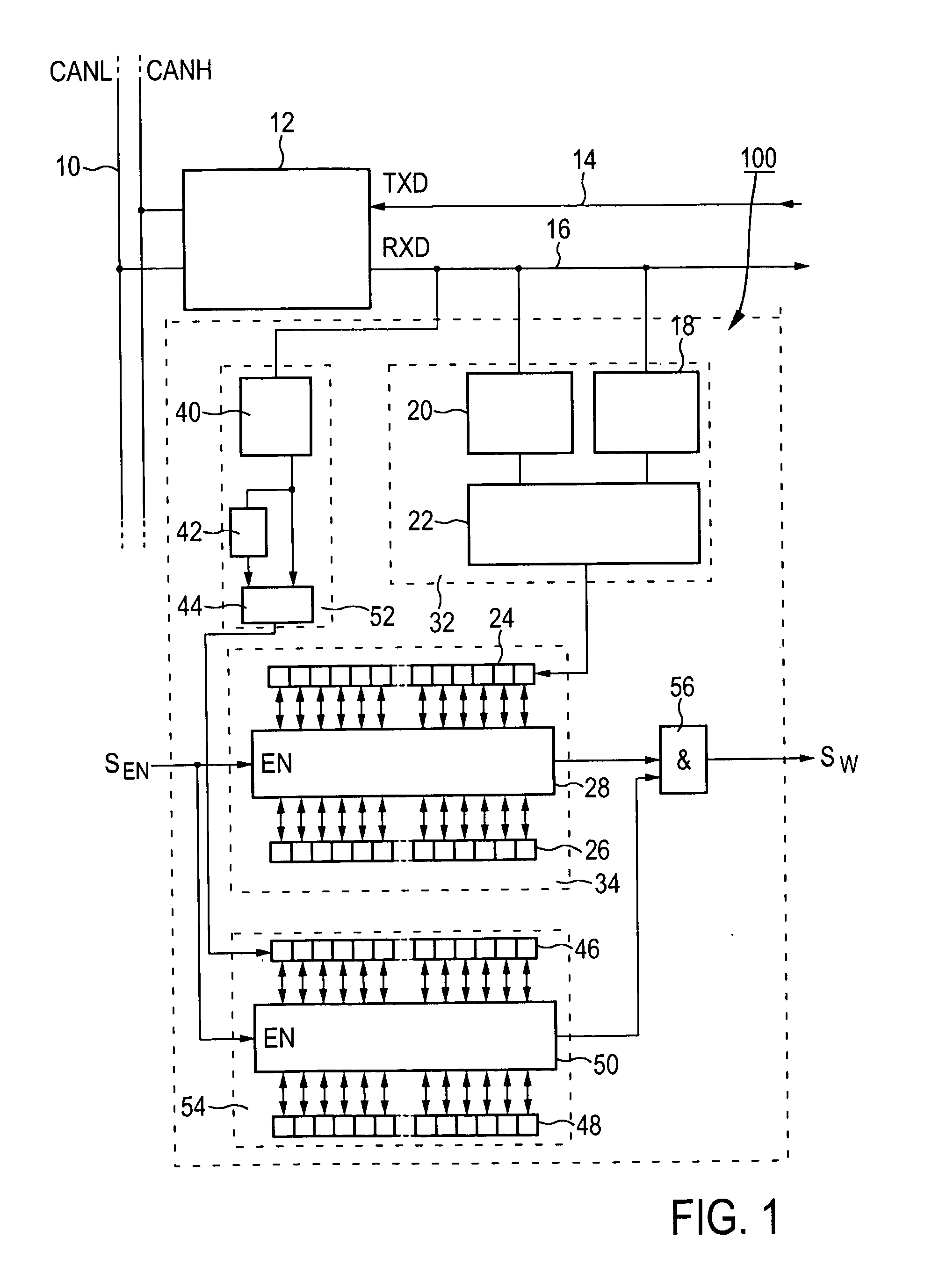
[0050]FIG. 1 shows a transceiver 12 connected to a CAN bus line 10 having CANL and CANH wires and coupled to a pattern detector 100. It is noted that the transceiver 12 and the pattern detector 100 may be combined to one single device or chip and integrated into system basis chips or other suitable configured ASICs. The rest of the bus node is connected to the CAN transceiver 12 by a data transmission (TXD) line 14 and a data reception (RXD) line 16.

[0051]A first decoder 32 comprises electronic circuits 18 and 20, connected to the RXD line 16, configured for measuring the length of successive recessive phas...


PUM


Abstract

A method of encoding a digital bus message information, in particular a wake-up bus message information or configuring data, on a bus system, the method comprising: encoding a predetermined part of digital bus message information bits by means of sub-patterns in a stream of line symbols on at least one bus line, wherein sub-patterns consist of successive dominant and recessive phases, comprised of recessive and dominant line symbols, wherein a recessive phase is comprised of at least two recessive line symbols in order to establish a ratio of successive dominant and recessive phases that corresponds to a value of the predetermined part. A respective digital bus message, particularly for use on a bus system, is to be encoded in accordance with the method.
Further, a bus node for a system bus having a plurality of stations that are coupled together by means of an arrangement of bus lines, comprises decoding circuitry configured for an analysis of sub-patterns in a stream of data on at least one bus line, and analysing circuitry configured to detect encoded digital bus message information, in particular a wake-up bus message information or configuring data, transmitted in a stream of line symbols on the bus system, wherein the digital bus message information is encoded in accordance with the method.

Description

FIELD OF THE INVENTION[0001]The invention relates to a bus system having a plurality of bus nodes that are coupled together by an arrangement of bus lines, each bus node comprising at least a transceiver and a bus protocol controller.[0002]Further, the invention relates to a method of encoding and / or decoding a digital bus message on such a bus system in which the digital message comprises at least one part that is encoded by sub-patterns in the bus signal. More particularly, the invention relates to the definition of wakeup bus messages that result in an improved pattern detection in such a bus system, as well as to particular message patterns adapted for improved detection.[0003]Furthermore, the invention also relates to a bus node for use in such a bus system, in particular such bus node may comprise a transceiver, a bus protocol controller, and a pattern detector for decoding such digital message(s) on such a bus system in which the digital message comprises at least one part th...

Claims


Application Information

Patent Timeline
Patent Type & Authority Applications(United States)
IPC IPC(8): G06F13/42
CPCH04L12/12H04L12/40032H04L12/40039H04L12/4135G06F1/3209H04L2012/40234H04L2012/40241H04L2012/40273Y02B60/34H04L2012/40215Y02D30/50H04L12/40H04L9/40
Inventor ELEND, BERND UWE GERHARD
Owner NXP BV
Why Eureka
Try Eureka