Laser Scanning Optical Device

a laser scanning and optical device technology, applied in the field of laser scanning optical devices, can solve the problems of deformation of the entire holder, inability to control the attitude of the light source,

Active Publication Date: 2012-11-01
KONICA MINOLTA BUSINESS TECH INC
View PDF2 Cites 0 Cited by
  • Summary
  • Abstract
  • Description
  • Claims
  • Application Information

AI Technical Summary

Benefits of technology

[0008]The present invention has been accomplished in view of the above-mentioned problems of the prior art, and the object thereof is to prevent deformation of a holder which happens when adjusting an installation attitude of a light source and improve accuracy of attitude control of the light source.
[0025]the first adjusting member is rotated about the optical axis to change the abutting position of the inclination conveying part on the inclined part, which makes the light source holder oscillate along the inclined part, thus adjusting the attitude of the light source.

Problems solved by technology

However, the force could deform the entire holder and inhibit accuracy of the control of the attitude of the light source.

Method used


Image

  • Laser Scanning Optical Device
  • Laser Scanning Optical Device
  • Laser Scanning Optical Device

Examples


first embodiment

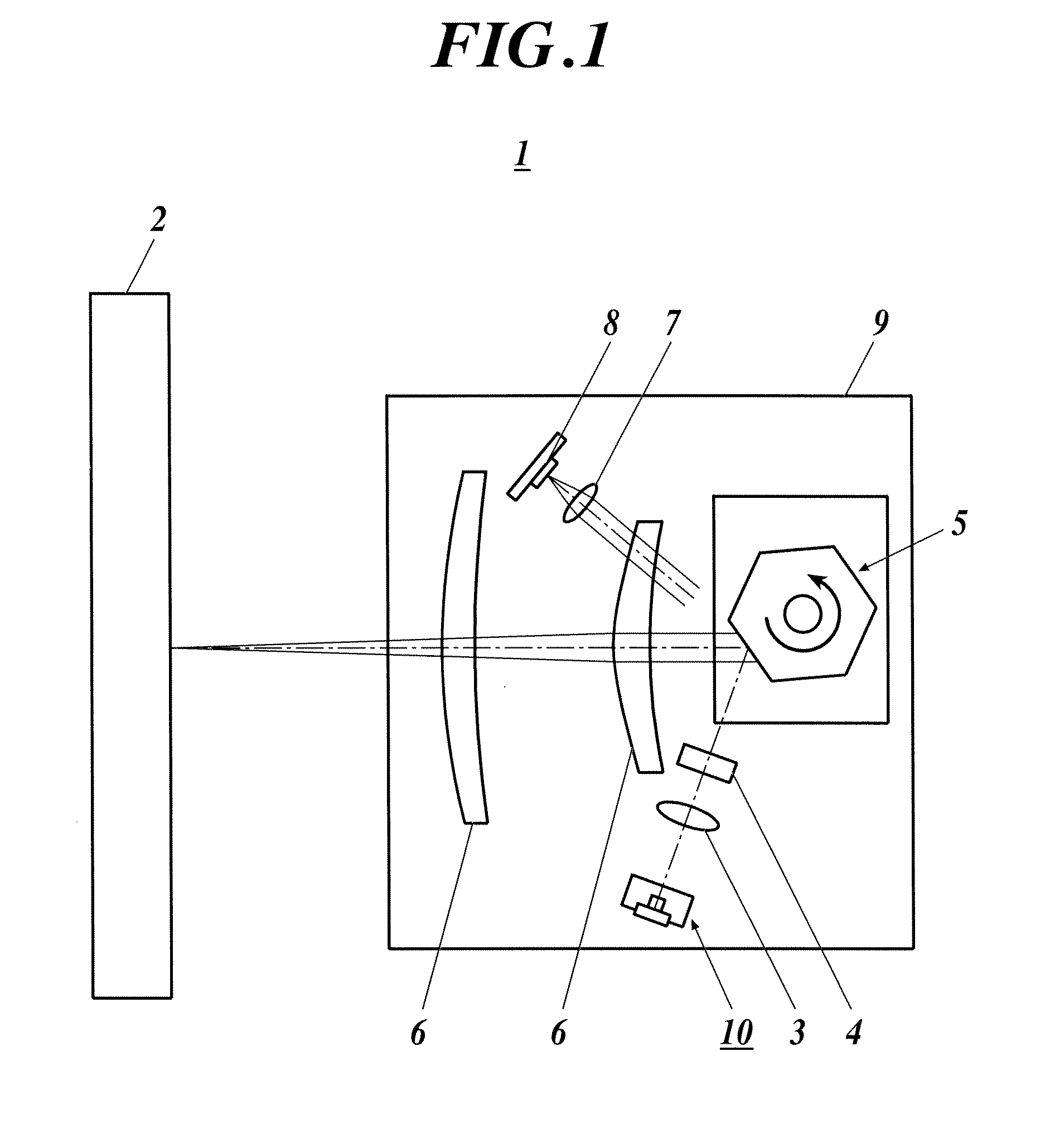
[0048]FIG. 1 is a schematic view showing a schematic structure of a laser scanning optical device according to this embodiment. As illustrated in FIG. 1, the laser scanning optical device 1 irradiates laser to a photoreceptor 2 to expose the photoreceptor 2 to light. The laser scanning optical device 1 is provided with a laser irradiating part 10 which irradiates laser, a first optical system 3 which converts diverging light generated in the laser irradiating part 10 into parallel light, a second optical system 4 which converts parallel light converted by the first optical system 3 into converging light only in the sub scanning direction, a polariscope 5 which polarizes the converging light converted by the second optical system 4, a third optical system 6 which condenses polarized laser onto the photoreceptor 2, a fourth optical system 7 for timing a starting position, and a sensor 8, which are all held by an optical housing 9.

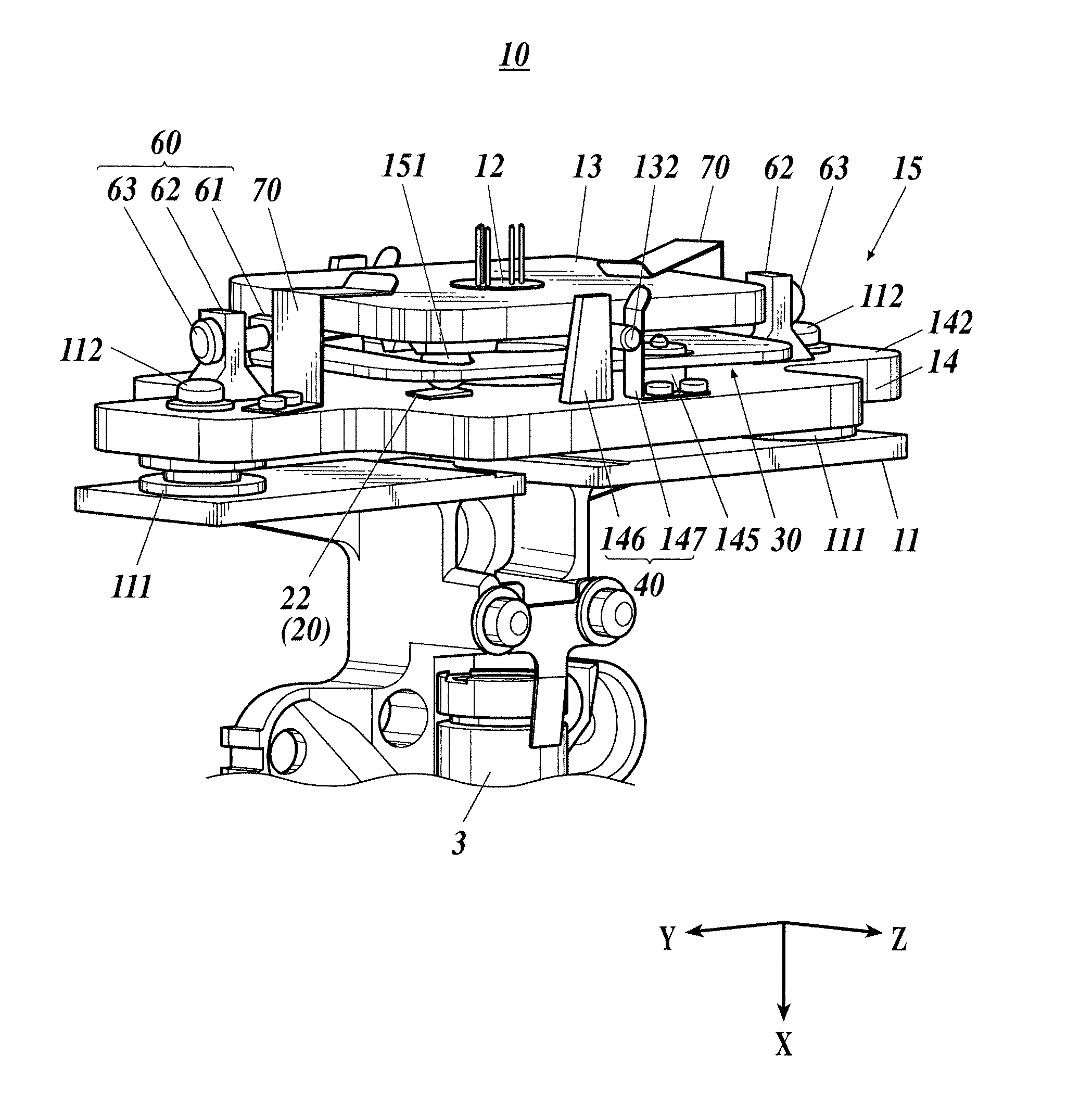
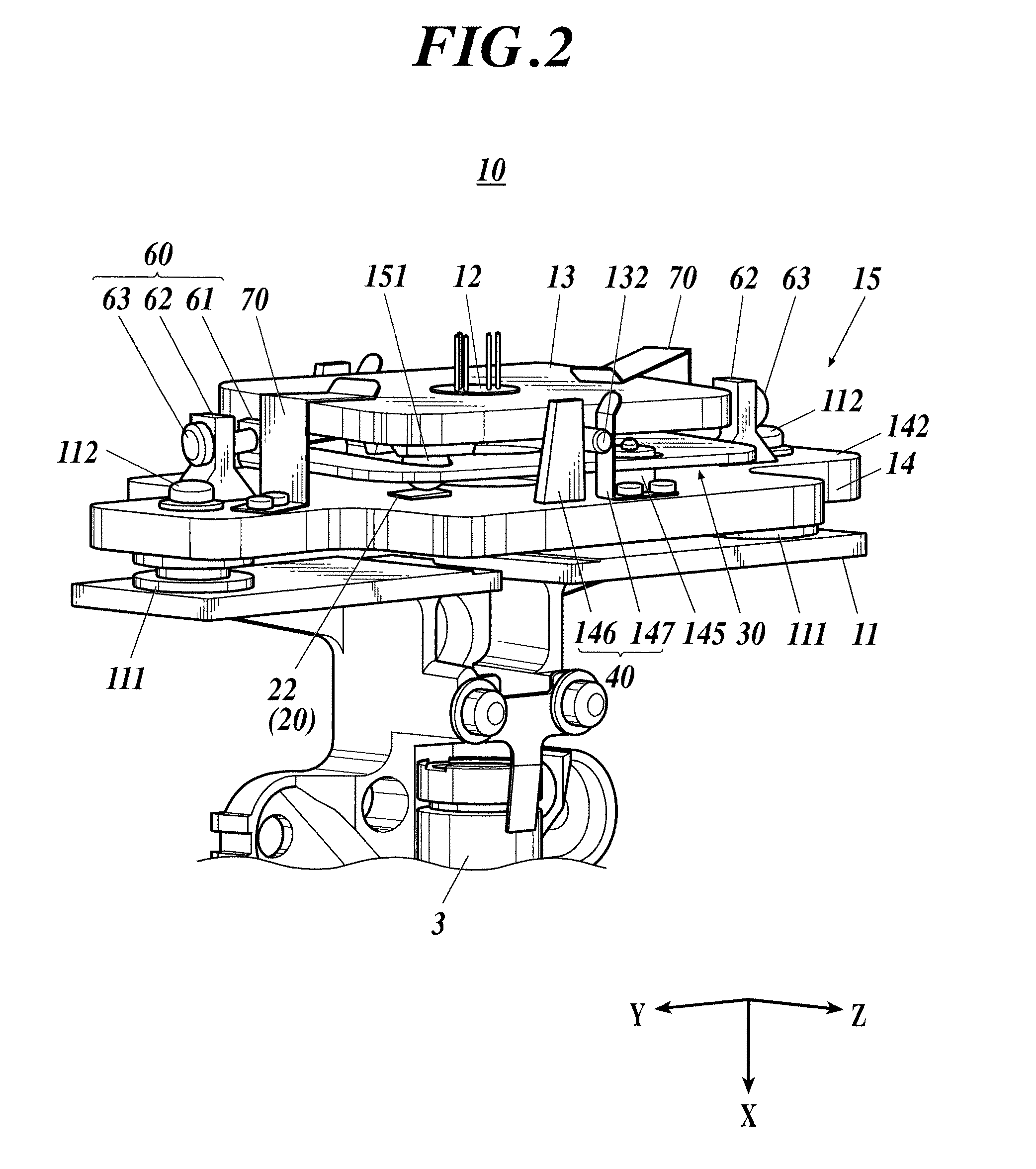
[0049]FIG. 2 is a perspective view showing a schematic ...

second embodiment

[0086]FIG. 14 is a schematic view showing a schematic structure of a laser scanning optical device according to this embodiment. As illustrated in FIG. 14, the laser scanning optical device 1A irradiates laser to a photoreceptor 2 to expose the photoreceptor 2 to light. The laser scanning optical device 1A is provided with a laser irradiating part 1000 which irradiates laser, a first optical system 3 which converts diverging light generated in the laser irradiating part 1000 into parallel light, a second optical system 4 which converts parallel light converted by the first optical system 3 into converging light only in the vertical scanning direction, a polariscope 5 which polarizes the converging light converted by the second optical system 4, a third optical system 6 which condenses polarized laser onto the photoreceptor 2, a fourth optical system 7 for timing a starting position, and a sensor 8, which are all held by an optical housing 9.

[0087]FIG. 15 is a front view showing a sc...


PUM


Abstract

A laser scanning optical device includes: alight source having a plurality of emission points; a plate-like light source holder which holds the light source in a center of the light source holder; a base arranged to face the light source holder; and an attitude adjusting part which adjusts an attitude of the light source by adjusting a tilt of the light source holder, and the attitude adjusting part includes an inclined part and an inclination conveying part, and adjusts the tilt of the light source holder with respect to the base by displacing an abutting position of the inclined part corresponding to the inclination conveying part along an inclined surface of the inclined part.

Description

CROSS-REFERENCE TO RELATED APPLICATION[0001]The present U.S. patent application claims a priority under the Paris Convention of Japanese patent application No. 2011-100376 filed on Apr. 28, 2011 and Japanese patent application No. 2011-100378 filed on Apr. 28, 2011 which shall be a basis of correction of an incorrect translation, and is incorporated by reference herein.BACKGROUND OF THE INVENTION[0002]1. Field of the Invention[0003]The present invention relates to a laser scanning optical device.[0004]2. Description of the Related Art[0005]Conventionally, in an image-forming device such as a laser printer and a digital copying machine, a laser scanning optical device is equipped thereto which performs scanning with laser in order to expose a photoreceptor to light.[0006]A laser scanning optical device is provided with a light source which irradiates laser and a holder which holds the light source. The holder is, for example, in an approximate plate shape, and the light source is mou...

Claims


Application Information

Patent Timeline
Patent Type & Authority Applications(United States)
IPC IPC(8): G02B26/10
CPCG02B26/12B41J2/473
Inventor TAJIMA, NAOKINAGASAKA, YASUSHITAKAHIRO, MATSUO
Owner KONICA MINOLTA BUSINESS TECH INC
Why Eureka
Try Eureka