
Method for adjusting the sensitivity of ultrasonic sensors

a technology of ultrasonic sensors and sensitivity adjustment, which is applied in the direction of transmission monitoring, instruments, measurement devices, etc., can solve the problems of not being able to detect the ground and the hint of an object at the distance of the spacing between the ground and the driver, and the method described, etc., to achieve the effect of reducing the cost of ultrasonic sensors

Active Publication Date: 2012-11-01
ROBERT BOSCH GMBH
View PDF3 Cites 13 Cited by
  • Summary
  • Abstract
  • Description
  • Claims
  • Application Information

AI Technical Summary

Benefits of technology

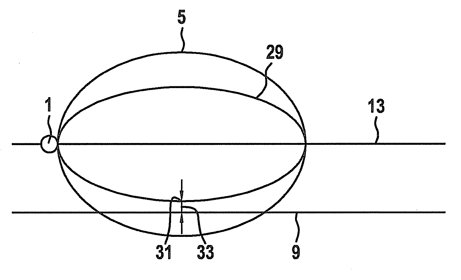
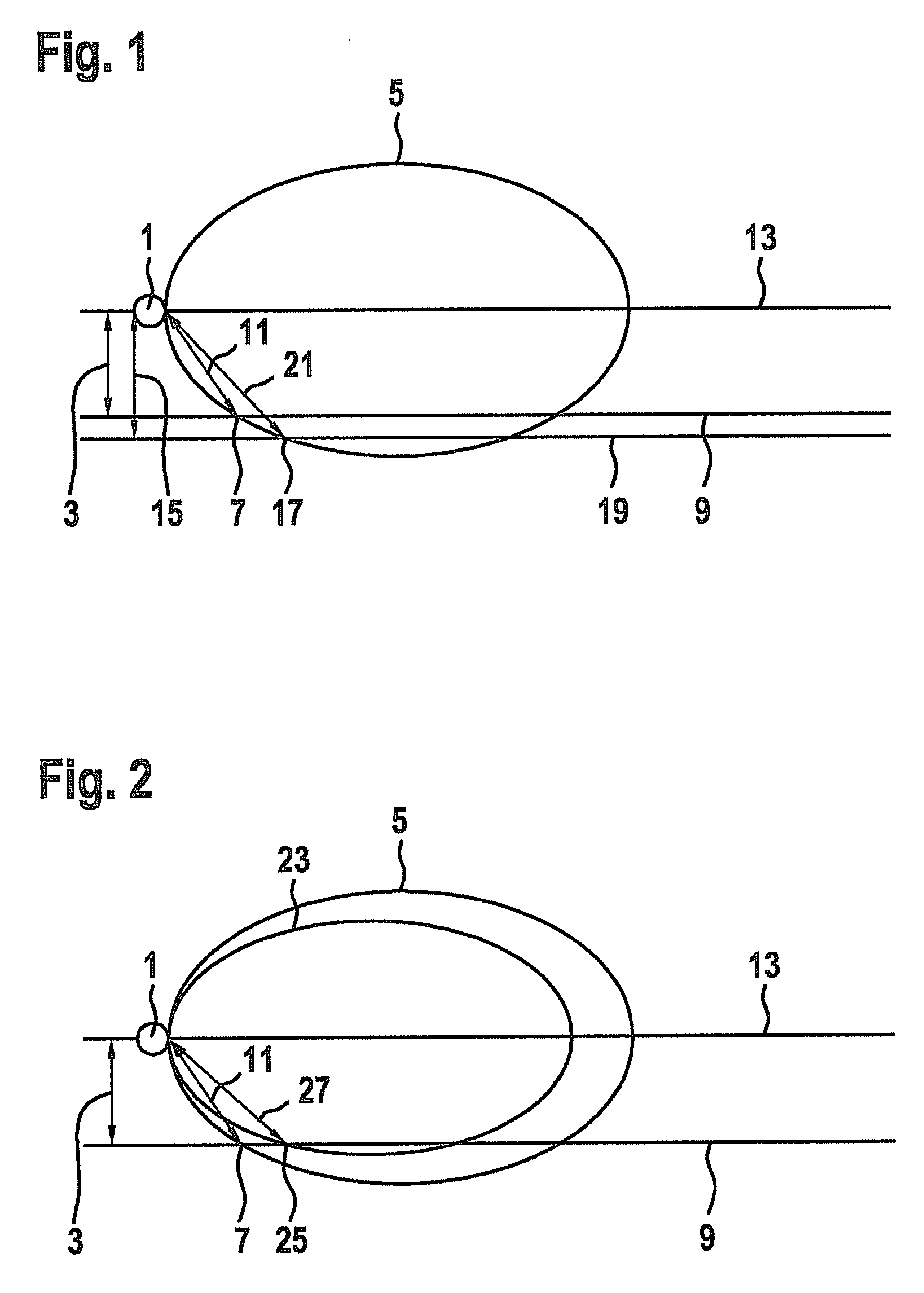
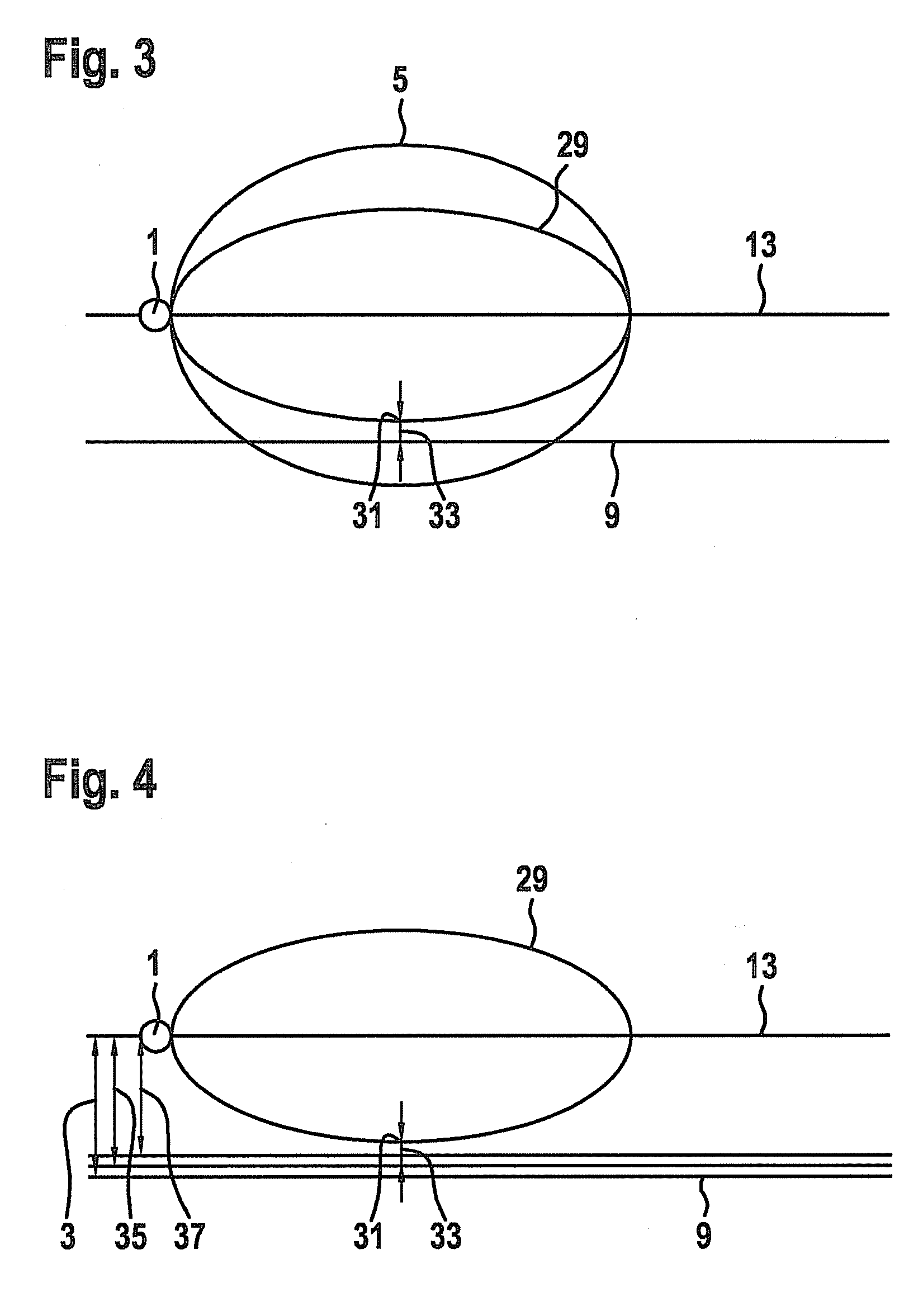
[0013]In one specific embodiment of the present invention, before adjusting the sensitivity of the ultrasonic sensor, the height of installation of the ultrasonic sensor is determined from the distance between the ultrasonic sensor and the intersection of the sonic lobe with the ground. This has the advantage that the adjustment of the sensitivity of the ultrasonic sensor is able to take place directly as a function of the height of installation. To do this, it is possible, for example, to store a characteristics curve in which the respective sensitivities of the ultrasonic sensor are assigned to the height of installation. However, since, at a constant aperture angle of the sonic lobe, the height of installation is a direct function of the distance of the intersection of the sonic lobe with the ground and the ultrasonic sensor, the adjustment of the sensitivity may, of course, also be ascertained directly from the distance, detected in step (b), between the intersection of the sonic lobe with the ground and the ultrasonic sensor.
[0020]In one preferred specific embodiment of the present invention, the verification of the setting of the sensitivity takes place continually during the operation of the vehicle. This has the advantage that, because of the continual verification, even differences in the height of installation, which come about, for example, because of differences in height, for instance, based on different loading states and / or load leveling systems of the vehicle, are able to be compensated for. The ultrasonic sensors are adjusted in each case as a function of the vehicle level which comes about, for instance, due to the loading state or a load leveling system.

Problems solved by technology

Since, however, the ground does not represent any obstacle, the detection of the ground and the hint of an object at a distance of the spacing from the ground to the driver is not desired.
The method described in DE-T 601 17 407 cannot be used on ultrasonic sensors, however.
In addition, the use in commercial vehicles, in particular, is possible only to a limited degree, since, on account of big differences in height because of varying loading states and / or the load leveling system of vehicles, the setting of the sensor would have to be adjusted in each case to the level of the vehicle, so as to prevent, at varying distances of the sensors from the ground, the roadway from being detected.
If the ground is detected, the adjusted sensitivity of the ultrasonic sensors is too high.
However, flat obstacles also have to be detected.
If the object were closer to the vehicle, this would lead to a faulty setting of the sensitivity of the ultrasonic sensors, and the sonic lobe set would have an intersection with the ground, so that in operation of the system, the ground would be detected.
If different heights of installation are yielded, the measurement has to be repeated, since at least one of the results is faulty.

Method used


Image

  • Method for adjusting the sensitivity of ultrasonic sensors
  • Method for adjusting the sensitivity of ultrasonic sensors
  • Method for adjusting the sensitivity of ultrasonic sensors

Examples


Embodiment Construction

[0029]FIG. 1 shows a schematic representation for determining distance at different heights of installation.

[0030]In order to set the sensitivity of an ultrasonic sensor 1, used for distance detection, in such a way that in the operation of a system using the ultrasonic sensor, for instance, of a system for parking support, the ground is not detected as being an obstacle, the sensitivity of ultrasonic sensor 1 has to be adjusted to its height of installation 3. At too high a sensitivity of ultrasonic sensor 1, a sonic lobe 5 emitted by ultrasonic sensor 1 is shaped so that it has an intersection 7 with the ground 9. This leads to the signal sent by ultrasonic sensor 1 being reflected by ground 9, and the reflected echo being received. In this way, ground 9 is also detected as an object in the range of ultrasonic sensor 1. Since ground 9, however, does not represent any obstacle, data on the distance of ground 9 from ultrasonic sensor 1 are not desired. For this reason, the sensitivi...


PUM


Abstract

A method for adjusting the sensitivity of ultrasonic sensors for detecting the distance of objects from a vehicle. A sensor sensitivity is set selected so that a sonic lobe is transmitted which has an intersection with the ground. A measurement is determined using the sensor, objects in the surroundings of the vehicle having a greater distance from the vehicle than the distance from the sensor to the intersection of the sonic lobe with the ground, so the distance from the sensor to the intersection of the lobe with the ground is detected as being the shortest distance from an object. The sensitivity of the sensor is set as a function of the distance between the sensor and the intersection of the lobe with the ground, so after sensitivity is set, the lobe, at its point closest to the ground, does not fall below a specified distance from the ground.

Description

FIELD OF THE INVENTION[0001]The present invention relates to a method for adjusting the sensitivity of ultrasonic sensors for detecting distances of objects from a vehicle.BACKGROUND INFORMATION[0002]Systems including distance-measuring sensors are particularly used in systems for parking support for a driver of a motor vehicle. Using the distance measuring sensors, the distance between the vehicle and an object is recorded. For this purpose, a signal is sent by the sensor in customary sensors and an echo reflected by an object is received. From the propagation time of the signal between the sending of the signal and the reception of the echo one is able to ascertain the distance of the object from the sensor. Sensors used for the distance measurement are currently ultrasonic sensors, radar sensors, infrared sensors or LIDAR sensors, for example.[0003]It is common to all these sensors that the signal, sent by an object that is located in the emission cone, is reflected and the echo ...

Claims


Application Information

Patent Timeline
Patent Type & Authority Applications(United States)
IPC IPC(8): G01S7/52G01S15/931
CPCG01S7/52004G01S2007/52012G01S15/931G01S15/08
Inventor KLOSS, FLORIAN
Owner ROBERT BOSCH GMBH
Learn More