Shock absorber

a technology of shock absorber and shock absorber, which is applied in the direction of braking discs, slip couplings, gearing, etc., can solve the problems of reducing the lifetime of the shock absorber, too abrupt change of friction factor to control the transmission torque, and inability to supply sufficient grease to the sliding surface of the disk

Inactive Publication Date: 2005-05-03
DENSO CORP
View PDF16 Cites 6 Cited by
  • Summary
  • Abstract
  • Description
  • Claims
  • Application Information

AI Technical Summary

Benefits of technology

[0011]The invention has been made in view of the above problem and has an object of providing a shock absorber that can make the height of the banks (or raised portions) of the rectangular dimples even.
[0012]According to a main feature of the invention, rotary disk of a shock absorber has a plurality of press-formed rectangular dimples at a surface opposite the stationary disk. The rectangular dimples have four sides that incline to a direction of rolling of the raw material of the rotary disk. In such a case, the difference in height between the four side banks can be effectively reduced so that four banks can touch the stationary disk evenly.

Problems solved by technology

This lowers the lifetime of the shock absorber.
If another two-side banks start touching the stationary disk after the first two side-banks initially touched the stationary disk have worn away, the friction factor changes too abruptly to control the transmission torque.
Accordingly, a sufficient amount of grease cannot be supplied to the sliding surfaces of the disks.
This causes the seizing and shortens the lifetime.

Method used


Image

  • Shock absorber
  • Shock absorber
  • Shock absorber

Examples


first embodiment

[0040

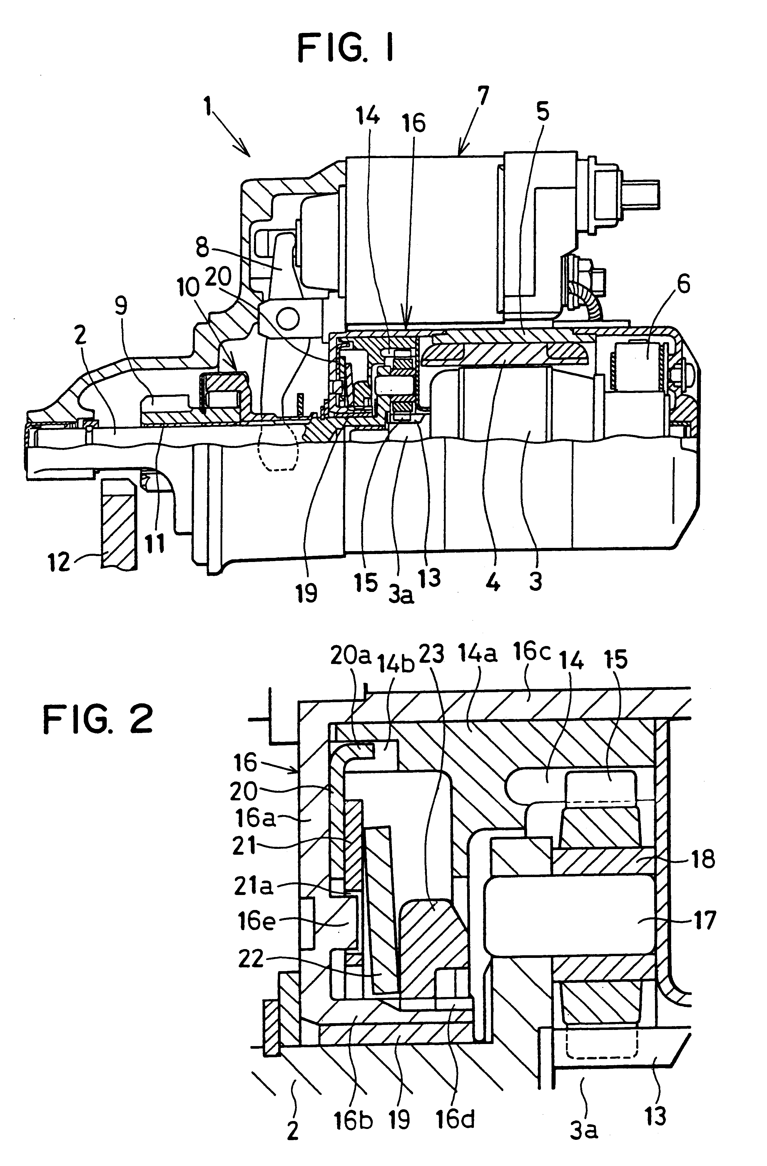
[0041]Shock absorber according to a first embodiment of the invention that is mounted into a starter is described with reference to FIGS. 1-4.

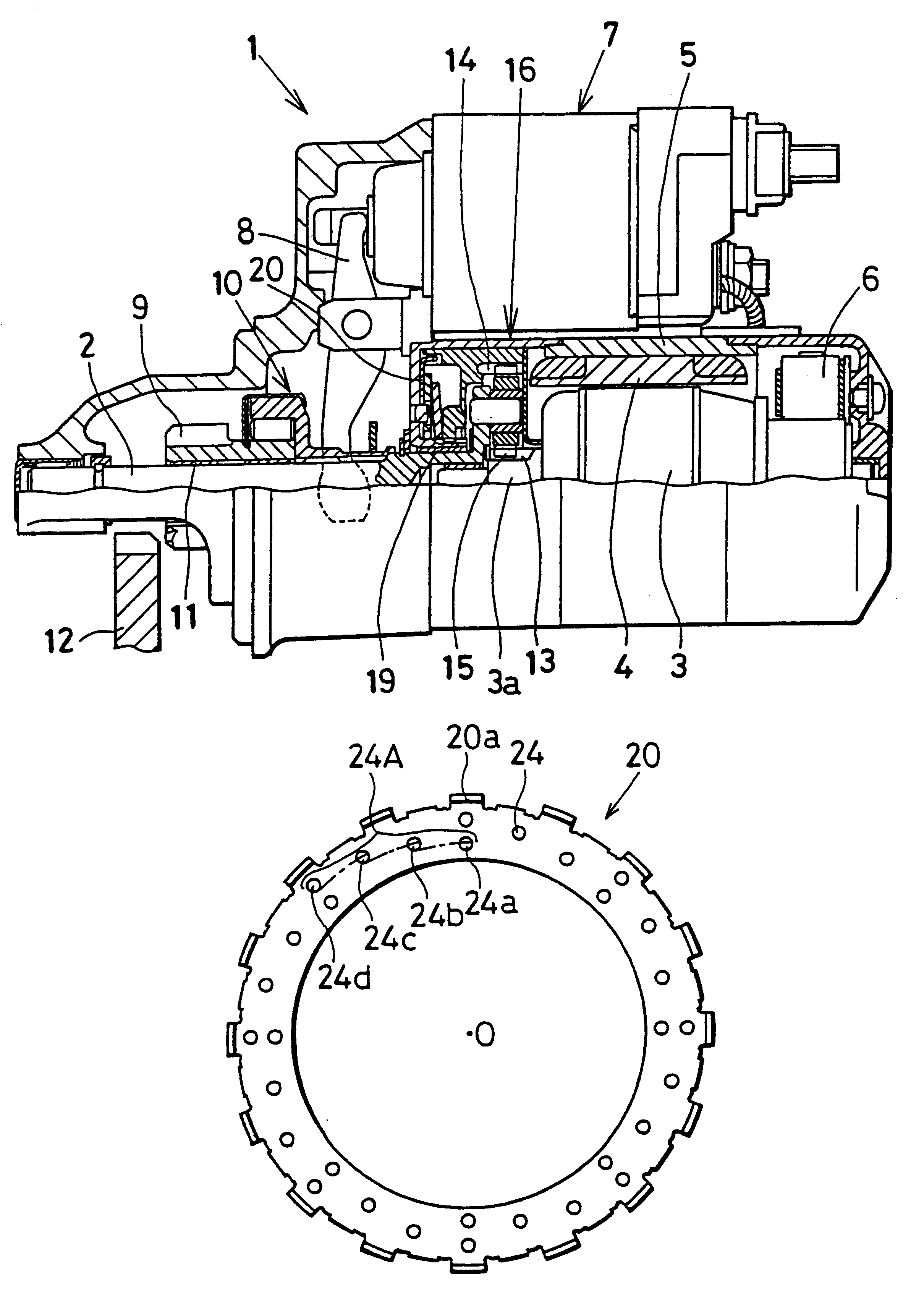
[0042]As shown in FIG. 1, starter 1 includes a speed reduction unit, output shaft 2 and a shock absorber according to a first embodiment of the invention. The speed reduction unit reduces the rotation speed of later described starter motor and transmits it to output shaft 2. The shock absorber absorbs an excessive torque or a shock applied to the speed reduction unit.

[0043]The starter motor is a well-known DC motor that is comprised of armature 3, stator poles 4, yoke 5 and brushes 6. When a key switch is turned on and a pair of internal contacts of magnet switch 7 is closed, armature 3 is energized through brushes 6 to rotate.

[0044]Magnet switch 7 opens or closes the internal contacts as a plunger (not shown) moves to drive pinion gear 9, together with one-way clutch 10, back and forth.

[0045]Pinion gear 9 is slidably fitted to the outer ...

second embodiment

[0072

[0073]A shock absorber according to a second embodiment of the invention will be described with reference to FIGS. 5A and 5B.

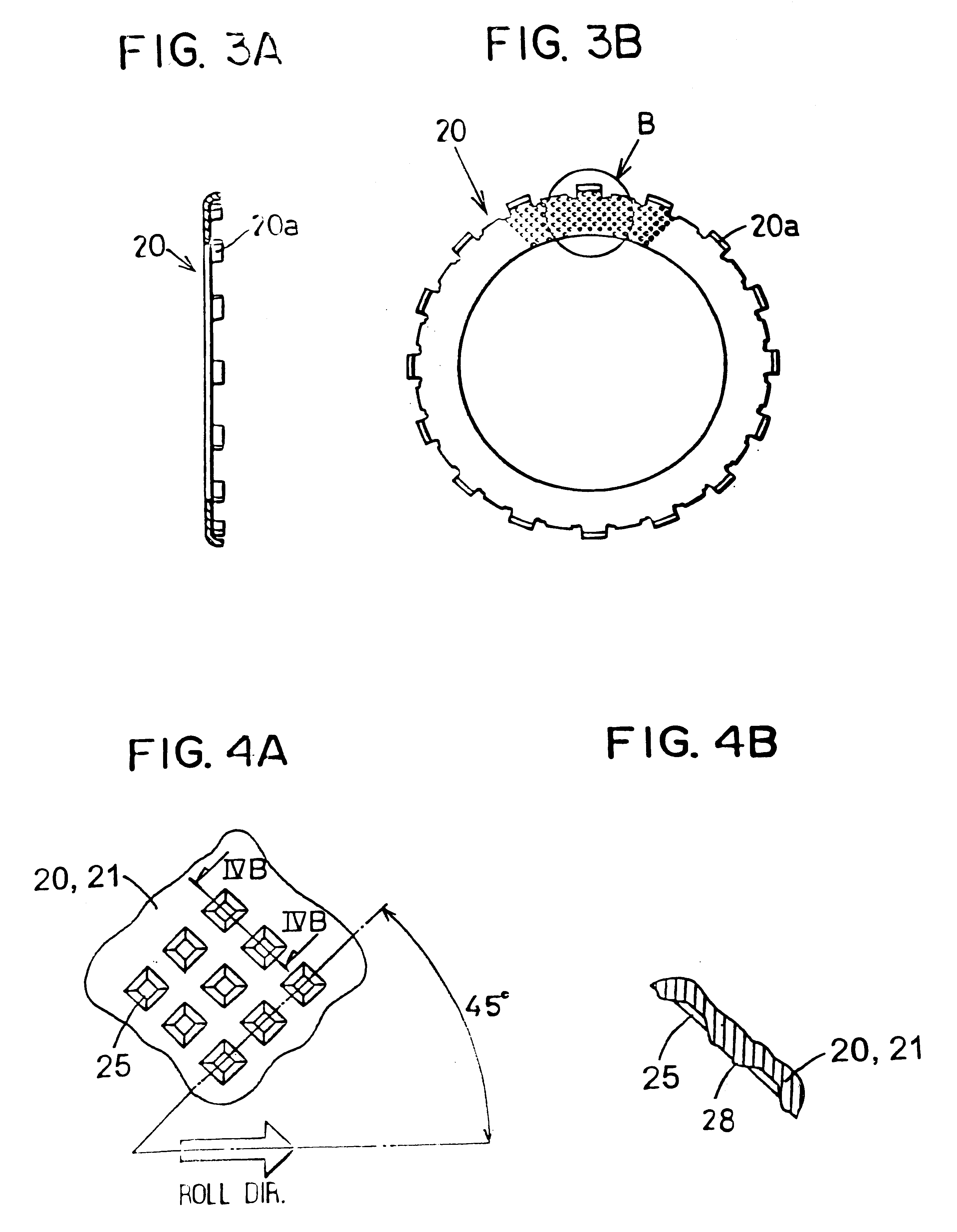
[0074]Rotary disk 20 is a press-formed metal ring. Rotary disk 20 is disposed in contact with front wall 16a and is detained in internal gear 14 by a plurality of claws 20a, which are formed at the circumference of outer wall 14a, respectively inserted into the plurality of recesses 14b.

[0075]A plurality of projections or banks (not shown) is formed at opposite surfaces of rotary disk 20 in the same manner as described with reference to FIGS. 3A and 3B. Banks 28 are formed when a plurality of dimples 25 (depressions / not shown) is press-formed at the surfaces of rotary disk 20.

[0076]In addition, rotary disk 20 has a plurality of oil holes 24 penetrating the same in the thickness direction. The plurality of oil holes 24 is disposed almost evenly in the circumferential direction. Each group of four circumferentially lined oil holes 24 forms a spiral line ab...

third embodiment

[0086

[0087]Rotary disk 20 of a shock absorber according to a third embodiment of the invention is described with reference to FIG. 6.

[0088]Oil holes at the inner peripheral edge (or the outer peripheral edge) of rotary disk 20 can open inward. In this case, the same effect as the second embodiment can be obtained.


PUM

PropertyMeasurementUnit
angleaaaaaaaaaa
frictionaaaaaaaaaa
circumferenceaaaaaaaaaa

Abstract

A shock absorber for a starter is presented. The shock absorber includes a rotary disk, a stationary disk and a disk spring. The rotary disk is pressed by the disk spring against a stationary disk to generate frictional force when the rotary disk is rotated by an excessive shock thereby absorbing the shock. The rotary disk has a plurality of press-formed rectangular dimples at a surface opposite the stationary disk, and each side of each the rectangular dimple inclines to a direction of rolling of the raw material of the rotary disk.

Description

CROSS REFERENCE TO RELATED APPLICATION[0001]This is a Division of application Ser. No. 09 / 654,546 filed Sep. 1, 2000 now U.S. Pat. No. 6,572,479. The entire disclosure of the prior application(s) is hereby incorporated by reference herein in its entirety.[0002]The present application is based on and claims priority from Japanese Patent Applications: Hei 11-300442, filed Oct. 22, 1999, Hei 11-300480, filed Oct. 22, 1999, Hei 11-300492, filed Oct. 22, 1999, and 2000-45589, filed Feb. 23, 2000, the contents of which are incorporated herein by reference.BACKGROUND OF THE INVENTION[0003]1. Field of the Invention[0004]The present invention relates to a shock absorber for absorbing a shock.[0005]2. Description of the Related Art[0006]JP-A-63-277859 discloses a starter equipped with a shock absorber for interrupting transmission of an excessive torque. In such a shock absorber for a starter, a rotary disk is pressed against a stationary disk to generate a frictional force so that rotation o...

Claims


Application Information

Patent Timeline
Patent Type & Authority Patents(United States)
IPC IPC(8): F02N15/02F02N15/04F16F15/139F16D65/12F16F15/131F16H35/10F16H35/00F16D69/00F02N15/06
CPCF02N15/046F02N15/063F16D65/12F16F15/1397F16H35/10F16D2065/1312Y10T74/132Y10S29/032F16D2069/004
Inventor SAITO, MIKIOKATOH, MASAHIROWAKAHARA, YASUYUKIHARUNO, KIYOKAZU
Owner DENSO CORP
Why Eureka
Try Eureka