Optical packet switching system

a packet switching and optical technology, applied in the field of optical packet switching systems, can solve the problems of no structure or mechanism with which to monitor error in the conventional packet switching scheme, waste of bandwidth corresponding to the waveform, and increase in bit error when the waveform is waveform

Inactive Publication Date: 2012-11-01
FUJITSU LTD
View PDF23 Cites 18 Cited by
  • Summary
  • Abstract
  • Description
  • Claims
  • Application Information

AI Technical Summary

Benefits of technology

[0009]The present invention has been made in view of the foregoing circumstances, and a purpose thereof is to provide an optical switching system capable of monitoring the signal quality in the optical transmission path.

Problems solved by technology

The IP packet does not transfer any significant information in the absence of data therein, so that the bandwidth corresponding thereto is wasted.
In this optical packet switching scheme, the bit error increases when the waveform of optical packet signal degrades on account of dispersion and non-linearity of optical transmission path.
Yet, no structure or mechanism with which to monitor error is available in the conventional packet switching scheme.
Thus arises a problem where the signal quality in optical transmission path cannot be monitored.

Method used


Image

  • Optical packet switching system
  • Optical packet switching system
  • Optical packet switching system

Examples


first embodiment

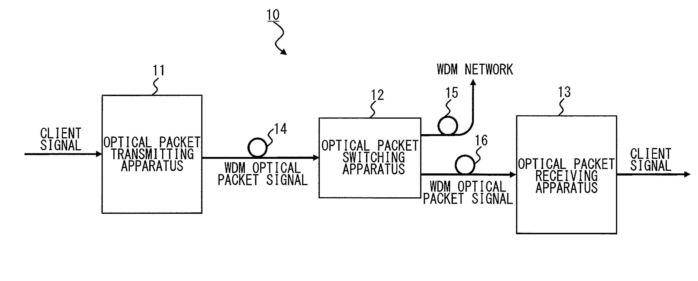
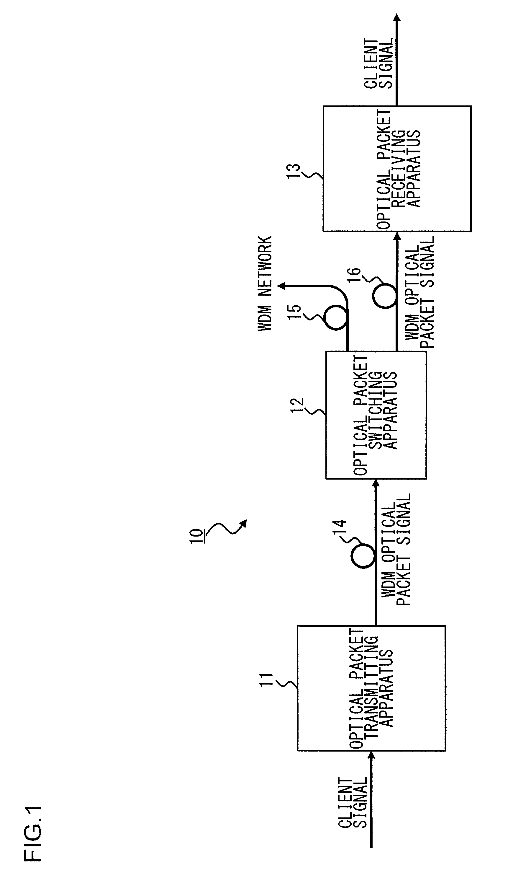
[0044]FIG. 1 illustrates an optical packet switching system 10 according to a first embodiment of the present invention. As shown in FIG. 1, the optical packet switching system 10 includes an optical packet transmitting apparatus 11, an optical packet switching apparatus 12 with one input and two outputs, an optical packet receiving apparatus 13, and first to third optical transmission paths 14 to 16.

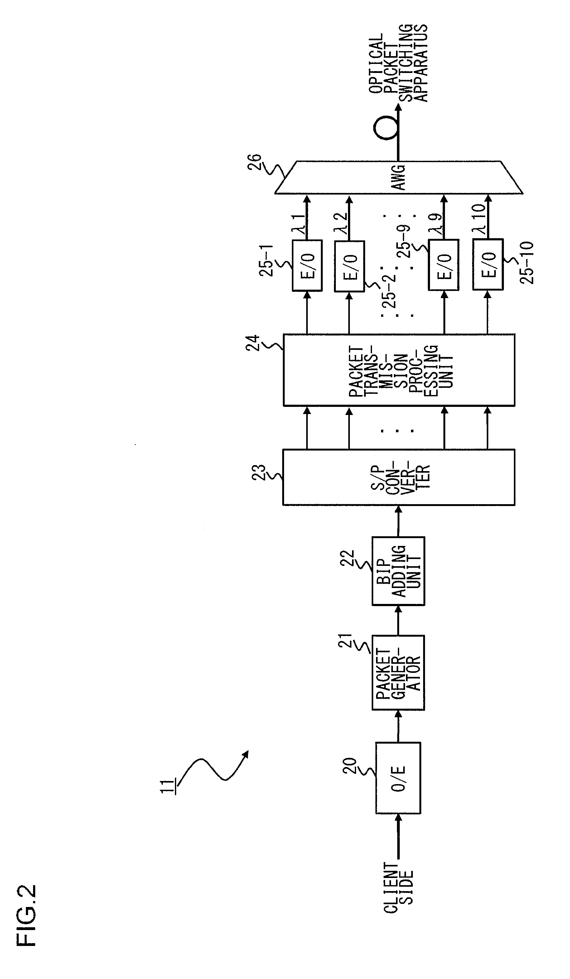
[0045]The optical packet transmitting apparatus 11 splits a client signal received from a client side into ten signals. Here, the client signal is 10 GEther (10 Gigabit Ethernet (registered trademark) packet signal), for example. Then the thus split ten data are loaded on optical signals of wavelengths λ1 to λ10 so as to generate optical packet signals of ten wavelengths. Then the optical packet signals of wavelength λ1 to λ10 are wavelength-multiplexed and outputted as WDM optical packet signals. Note that although the division number of the client signal and the number of wavelengths ...

second embodiment

[0072]A description is now given of an optical packet switching system according to a second embodiment of the present invention.

[0073]FIG. 6 illustrates a structure of an optical packet transmitting apparatus 11 according to a second embodiment of the present invention. Components of the optical packet switching system according to the present embodiment which are identical to or correspond to those of the optical packet switching system shown in FIG. 1 to FIG. 5 are given the same reference numerals herein and the repeated description thereof are omitted as appropriate.

[0074]The optical packet transmitting apparatus 11 according to the present embodiment differs from that according to the first embodiment of FIG. 2 in that ten BIP adding units (first to tenth BIP adding units 22-1 to 22-10) are provided subsequent to the serial / parallel converters 23.

[0075]In the present embodiment, the BIP adding units 22-1 to 22-10 each computes the bit interleaved parity (BIP) of each of the di...

third embodiment

[0079]A description is now given of an optical packet switching system according to a third embodiment of the present invention.

[0080]FIG. 8 illustrates a structure of an optical packet transmitting apparatus 11 according to the third embodiment of the present invention. The optical packet transmitting apparatus 11 according to the present embodiment differs from that according to the first embodiment of FIG. 2 in that an FEC (forward error correction) adding unit 27 is provided in substitution for the BIP adding unit.

[0081]The FEC adding unit 27 computes an FEC code of a packet signal inputted from the packet generator 21 and adds the computation result to this packet signal. FIG. 9 is a diagram showing a data format of packet signal according to the third embodiment of the present invention. As shown in FIG. 9, each packet signal includes a data area, a header provided before the data area, and a frame check sequence (FCS) provided after the data area. As shown in FIG. 9, the FEC ...


PUM


Abstract

An optical packet switching apparatus includes an optical packet switching apparatus, an optical transmitting apparatus, and an optical packet receiving apparatus. The optical packet transmitting apparatus includes a packet generator for generating a packet signal by adding the routing information to a received client signal, a BIP adding unit for adding BIP to the generated packet signal, and an electrical-to-optical converter for converting the packet signal, to which the BIP has been added, into an optical packet signal so as to be sent out. The optical packet receiving apparatus includes an electrical-to-optical converter for converting the received optical packet signal into an electrical packet signal, and a BIP comparison unit for detecting the error occurrence in the packet signal, based on the BIP added to the packet signal.

Description

BACKGROUND OF THE INVENTION[0001]1. Field of the Invention[0002]The present invention relates to an optical packet switching system which enables packet switching for each optical packet by switching an optical switch according to routing information given to an optical packet signal.[0003]2. Description of the Related Art[0004]In optical transmission systems employing wavelength division multiplexing (WDM), a technique that performs the path switching per wavelength by the use of a wavelength selective switch (WSS) and the like is put to practical use. As a technology that may succeed this technique, an optical packet switching method is now being investigated. In this optical packet switching method, an IP packet (10 GEther (10 Gigabit Ethernet (registered trademark) signal and the like), for example, is used as a small unit with which the switching is performed, and each is converted into the form of an optical packet and then the route is switched by an ultrahigh-speed optical p...

Claims


Application Information

Patent Timeline
Patent Type & Authority Applications(United States)
IPC IPC(8): H04B10/08H04J14/02H04B10/07H04B10/27H04B10/524H04B10/54H04B10/58
CPCH04J14/0267H04J14/0212
Inventor KITAJIMA, KOSHIFUKUTOMI, SATOSHIKAWASAKI, WATARU
Owner FUJITSU LTD
Why Eureka
Try Eureka