Lubricating oil composition

a technology of lubricating oil and composition, which is applied in the direction of lubricant composition, petroleum industry, additives, etc., can solve the problem that the lubricating oil composition disclosed in the patent literature 2 is not sufficient in electrical insulation properties, and achieves excellent resistance to wear

Active Publication Date: 2012-11-01
IDEMITSU KOSAN CO LTD
View PDF4 Cites 20 Cited by
  • Summary
  • Abstract
  • Description
  • Claims
  • Application Information

AI Technical Summary

Benefits of technology

[0007]Accordingly, an object of the invention is to provide a lubricating oil composition that

Problems solved by technology

Likewise, even the lubricating oil composition disclosed in Patent

Method used


Image

  • Lubricating oil composition
  • Lubricating oil composition
  • Lubricating oil composition

Examples


examples

[0044]Next, the invention will be further described in detail based on Examples, which by no means limit the invention. The properties (volume resistivity, resistance to wear between metal-metal, and solubility) of the lubricating oil composition (sample oil) of each of Examples were measured by the following methods.

(1) Volume Resistivity

[0045]In accordance with a method defined in JIS C2101, the volume resistivity of each sample oil was measured under test conditions such as a measurement temperature of 80 degrees C., an applied voltage of 250 V, and a measurement time of one minute. It should be noted that when a sample oil exhibits a volume resistivity of 5×10¹⁰ Ωm or more, it is judged that the volume resistivity of the sample oil is sufficiently high.

(2) Resistance to Wear Between Metal-Metal

(i) Shell Four Ball Wear Test

[0046]For evaluating resistance to wear between metal-metal, a wear track diameter was measured under test conditions such as a rotation speed of 1800 rpm, a m...


PUM


Abstract

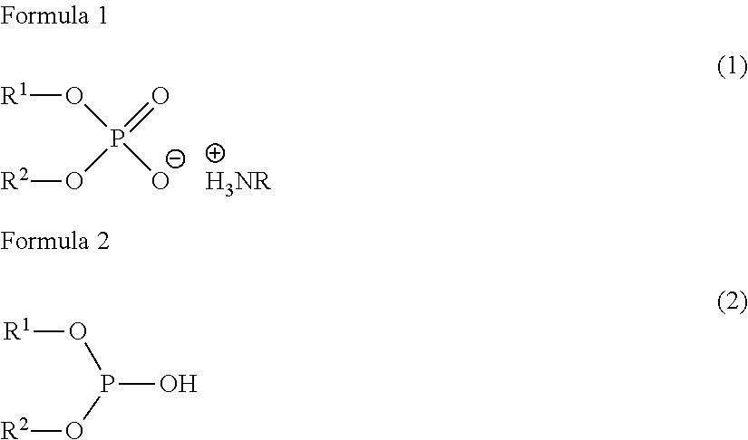
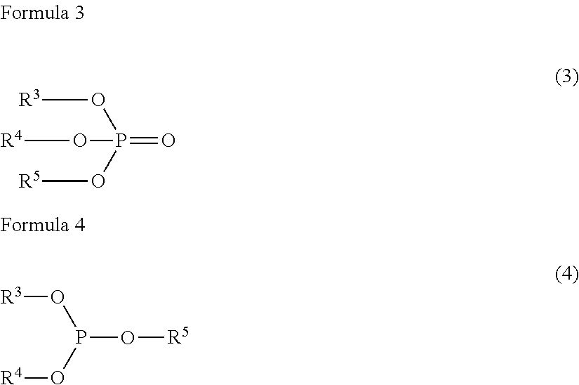
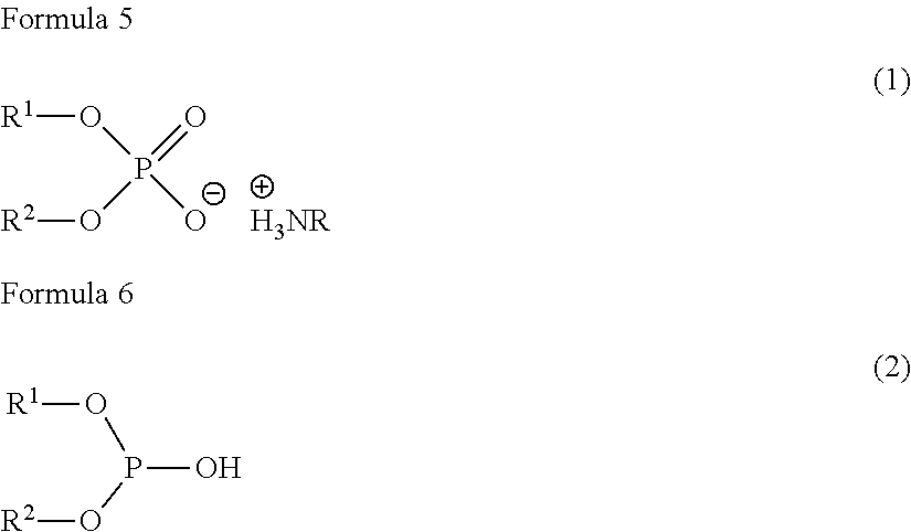
A lubricating oil composition contains: at least one lubricating base oil selected from the group consisting of a mineral lubricating base oil and a synthetic lubricating base oil; (a) a neutral phosphorus compound; (b) at least one acid phosphorus compound selected from the group consisting of a specific acid phosphate amine salt and a specific acid phosphite; and (c) a sulfur compound.

Description

TECHNICAL FIELD[0001]The present invention relates to a lubricating oil composition. In particular, the present invention relates to a lubricating oil composition used for a motor, a battery, an inverter, an engine, an electric cell or the like in a hybrid vehicle or an electric vehicle.BACKGROUND ART[0002]Recently, CO2 reduction has been strongly required for global environmental protection, so that technologies to fuel-efficient have been vigorously developed in the automotive field. Such technologies to fuel-efficient are mainly related to hybrid vehicles and electric vehicles, which will be rapidly becoming popular in the future. Hybrid vehicles and electric vehicles include an electric motor and a generator and are partly or entirely driven by the electric motor. An oil-cooling type can be employed to cool the electric motor in hybrid vehicles or electric vehicles. In this case, typical automatic transmission fluid (ATF) or continuously variable transmission fluid (CVTF) is usu...

Claims


Application Information

Patent Timeline
IPC IPC(8): C10M135/36C10M137/08C10M137/02
CPCC10M141/10C10M2223/00C10M2219/083C10M2219/106C10M2223/04C10M2223/041C10M2223/043C10M2223/045C10M2223/049C10N2220/022C10N2230/06C10N2230/42C10N2230/43C10N2230/70C10N2240/04C10N2240/042C10N2240/045C10N2240/201C10M2203/1006C10M2219/00C10N2210/02C10N2020/02C10N2030/06C10N2040/04C10N2040/16C10N2030/42C10N2030/43C10N2030/70C10N2040/042C10N2040/045C10N2010/04C10M135/00C10M137/02C10M137/08C10M157/08
Inventor DESHIMARU, JUNICHI
Owner IDEMITSU KOSAN CO LTD
Why Eureka
Try Eureka