Knee joint supporter

a supporter and joint technology, applied in the field of knee joint supporters, can solve the problems of difficulty in walking, sitting, walking, and rising from a chair, and achieve the effect of ensuring stability

Active Publication Date: 2012-11-01
KOWA CO LTD
View PDF1 Cites 42 Cited by
  • Summary
  • Abstract
  • Description
  • Claims
  • Application Information

AI Technical Summary

Benefits of technology

[0011]Advantageous Effects of Invention In the knee joint supporter according to the invention, by holding the knee region by the supporting ...

Problems solved by technology

The lowering of the muscular power (in particular, the quadriceps femoris muscle) of the knee joint...

Method used


Image

  • Knee joint supporter
  • Knee joint supporter
  • Knee joint supporter

Examples


first embodiment

of the Invention

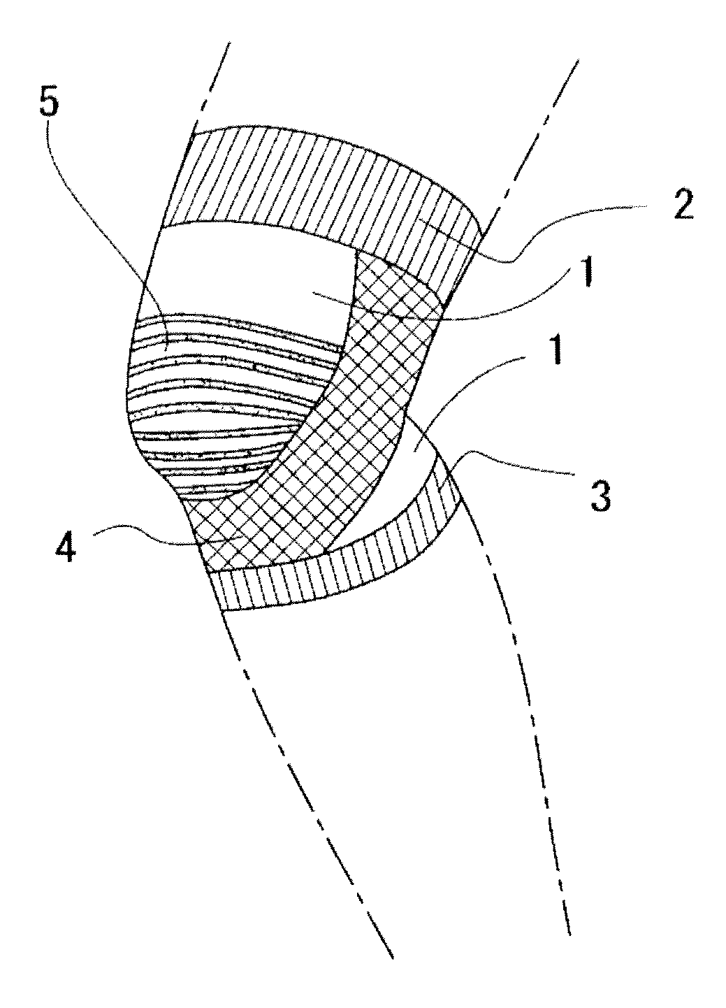
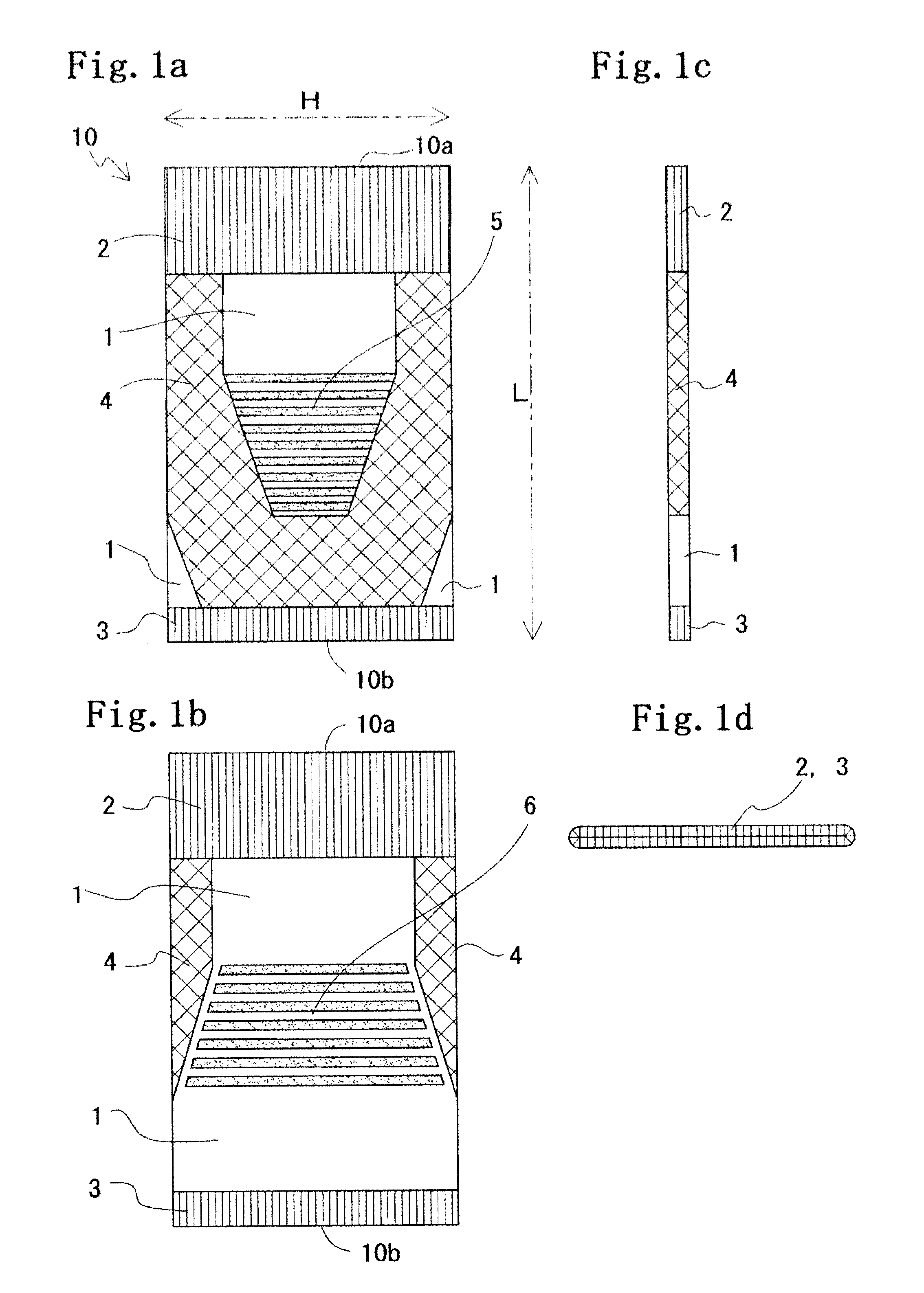
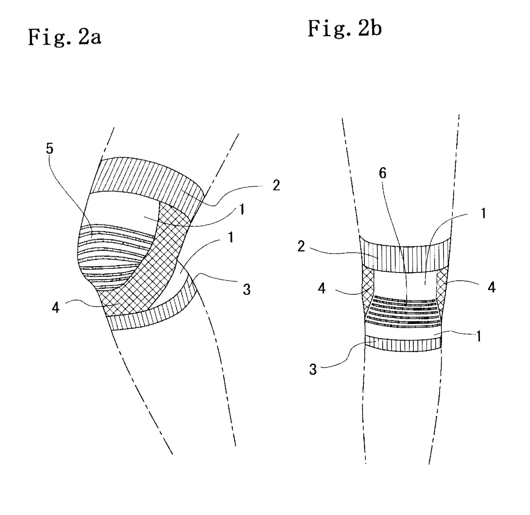
[0020]In FIGS. 1, 2, and 6 or 7, a knee joint supporter 10 is made of a tubular knitted fabric which is knitted in circular knitting by a hosiery knitting machine (for example, a type of knitting machine (number of needles: 256) manufactured by Lonati Co.), and is a supporter which comes into close contact with the body surface of a wearer, thereby assisting the knee joint of the wearer.

[0021]The knee joint supporter 10 has a desired functionality such as a taping function by performing different knitting with respect to a base fabric section 1 that is a stretchable knitted fabric which is knitted in a plain stitch, a rib stitch, a tuck stitch, a float stitch, a pile stitch, or the like by using an upper thread, an under thread, and a rubber thread as knitting yarn.

[0022]In addition, the base fabric section 1 related to this embodiment is a knitted fabric which is knitted in a rib stitch (hereinafter referred to as a rib stitch knitted fabric).

[0023]Further, the knee...

second embodiment

of the Invention

[0073]FIG. 8(a) is a front view showing the schematic configuration of a knee joint supporter related to the second embodiment. In FIG. 8(a), the same symbol as that in FIGS. 1, 2, and 6 or 7 denotes the same or equivalent section, and explanation thereof is omitted.

[0074]In FIG. 8(a) described above, the knee joint supporter 10 related to this embodiment is configured to have, in addition to the configuration in the first embodiment described above, a curling prevention section 8 which is made of a second tubular knitted fabric that is knitted in circular knitting continuously from the first anchor section 2 of the tubular knitted fabric, and which is knitted to be widened from one end 8a to the other end 8b of the second tubular knitted fabric.

[0075]The curling prevention section 8 is considered as being formed of, for example, a flexible amerib stitch knitted fabric.

[0076]Here, a float stitch knitted fabric is a knitted fabric in which a specific needle is put at ...

third embodiment

of the Invention

[0081]FIG. 8(b) is a right side view showing the schematic configuration of a knee joint supporter related to the third embodiment, and FIG. 8(c) is a plan view and bottom view of the knee joint supporter shown in FIG. 8(b). In FIGS. 8(b) and 8(c) the same symbol as that in FIGS. 1, 2 and 6 or 7 denotes the same or equivalent section, and explanation thereof is omitted.

[0082]In FIG. 8(b) described above, the knee joint supporter 10 related to this embodiment is configured to have, in addition to the configuration in the first embodiment described above, an elastic bone member 11 which is formed of an approximately rod-shaped body having flexibility and resiliency and disposed at a given place of the knee joint supporter 10 to approximately conform a longitudinal direction thereof to the length direction L of the knee joint supporter 10 and have a length extending over approximately the entirety of the length direction L.

[0083]Further, the knee joint supporter 10 is c...


PUM


Abstract

A knee joint supporter which can improve the stability of the knee joint, reduce the wearer's fatigue and reduce the load on the patellar tendon includes a first anchor section formed by wrapping one end of a tubular knitted fabric around the wearer's thigh to tighten it with the fabric, a second anchor section formed by wrapping the other end of the fabric around the wearer's lower thigh to tighten it with the fabric, and a substantially U-shaped knitted supporting section joined to the first anchor section, covering the wearer's patella region and thus supporting the wearer's patella. In the circumferential direction of the fabric, the stretch resistance of the two anchor parts are larger than the stretch resistance of a base fabric section. In the length width direction of the fabric, the stretch resistance of the supporting section is larger than the stretch resistance of the base fabric section.

Description

TECHNICAL FIELD[0001]The present invention relates to a knee joint supporter which can support wearer's daily motion, and particularly, to a knee joint supporter having a taping function of improving the stability of the knee joint, thereby reducing the fatigue of a wearer and also reducing a load on the patellar tendon.BACKGROUND ART[0002]The lowering of the muscular power (in particular, the quadriceps femoris muscle) of the knee joint makes daily motion such as walking, rising from a chair, seating, or going up and down stairs difficult.[0003]Further, in a state where the muscular power is lowered or a state of relative lack of the muscular power (a case where a muscle is overloaded in the balance between operation action and muscular power), support is performed by a passive element (the tendon, the ligament, or the like), and abrasion of the articular cartilage or inflammation of the tendon or the ligament is caused by repeating the support by the passive element. In particular...

Claims


Application Information

Patent Timeline
IPC IPC(8): A61F13/06
CPCA41D13/065A61F2002/7645A61F5/0109A61F2/68A61F5/0123A61F2210/0057D04B1/102D04B1/22D10B2509/028A41D13/00A41D13/06A61C1/00A61F5/02A61F13/00A61F13/08A61F13/14
Inventor MATSUO, KAZUHIKOKOGA, HIDEFUMI
Owner KOWA CO LTD
Why Eureka
Try Eureka