
Injection device and internal combustion engine

a technology of injection device and internal combustion engine, which is applied in the direction of machines/engines, electric control, combustion air/fuel air treatment, etc., can solve the problems of high exhaust gas rate in the cold start phase and significant cold start problems with the use of such fuels, and achieve the effect of reducing the throughput quantity of fuel and reducing the emissions of exhaust gas

Active Publication Date: 2012-11-08
ROBERT BOSCH GMBH
View PDF8 Cites 10 Cited by
  • Summary
  • Abstract
  • Description
  • Claims
  • Application Information

AI Technical Summary

Benefits of technology

The present invention relates to an injection device and an internal combustion engine that improve cold start characteristics and reduce exhaust gas emissions. The injection device includes two separate injection valves that promote a homogeneous and stable combustion of the injected fuel, even at low temperatures. The use of a heating device further improves the cold start phase and stability of the combustion process. The internal combustion engine can use alternative fuels without compromising performance, and the injection device can be used in various types of vehicles. The technical effects of the invention include improved fuel efficiency, reduced emissions, and faster and more reliable cold start phase.

Problems solved by technology

However, significant cold start problems arise with the use of such fuels.
In particular with the use of a fuel made up of 100% bioethanol, depending on the particular engine characteristics, significant starting difficulties can occur already below a temperature boundary of approximately 15° C., additionally forming high exhaust gas rates in the cold start phase.

Method used


Image

  • Injection device and internal combustion engine
  • Injection device and internal combustion engine
  • Injection device and internal combustion engine

Examples


Embodiment Construction

[0030]In the various Figures, identical parts have always been provided with the same reference characters, and are therefore as a rule each only named or mentioned once.

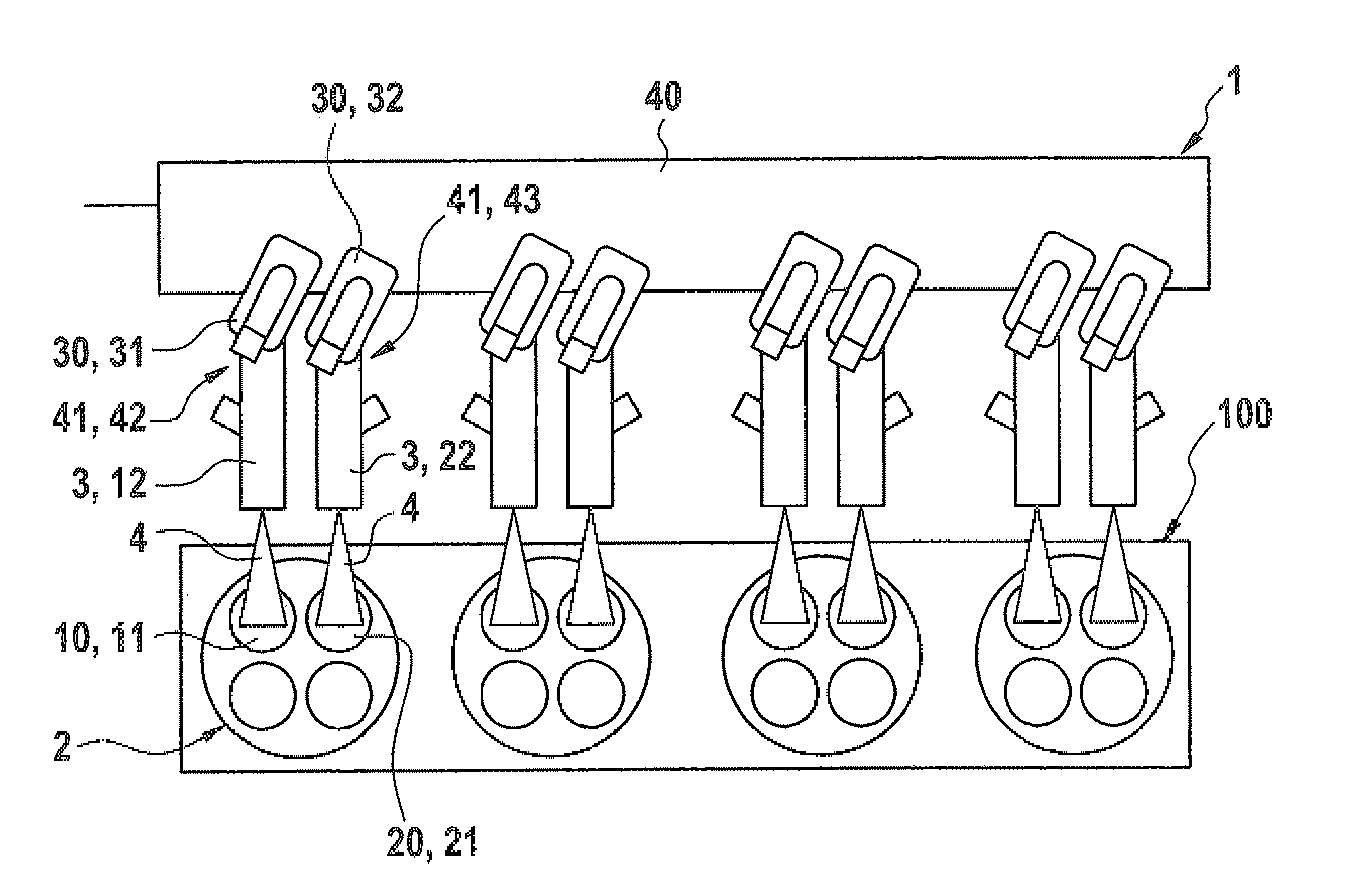
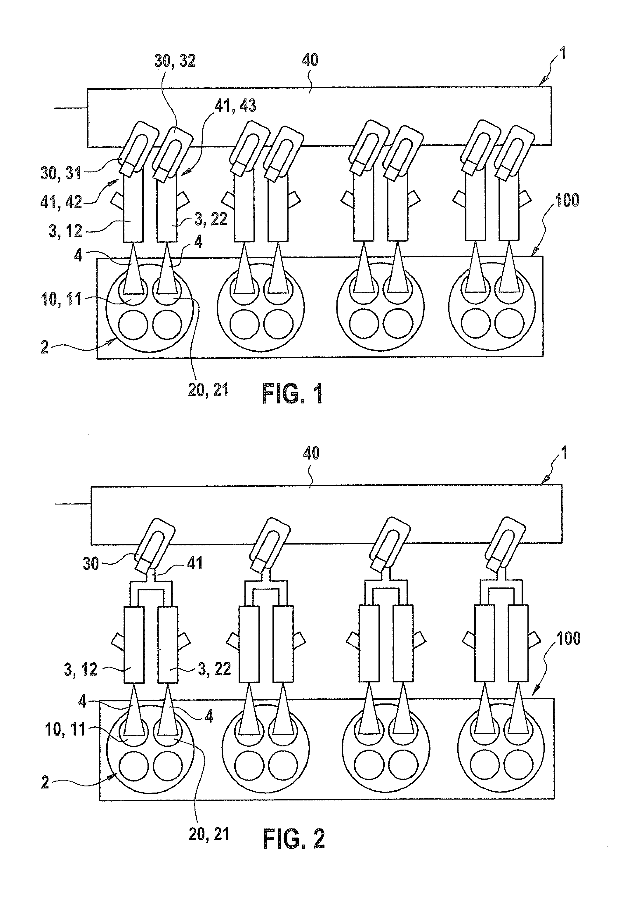
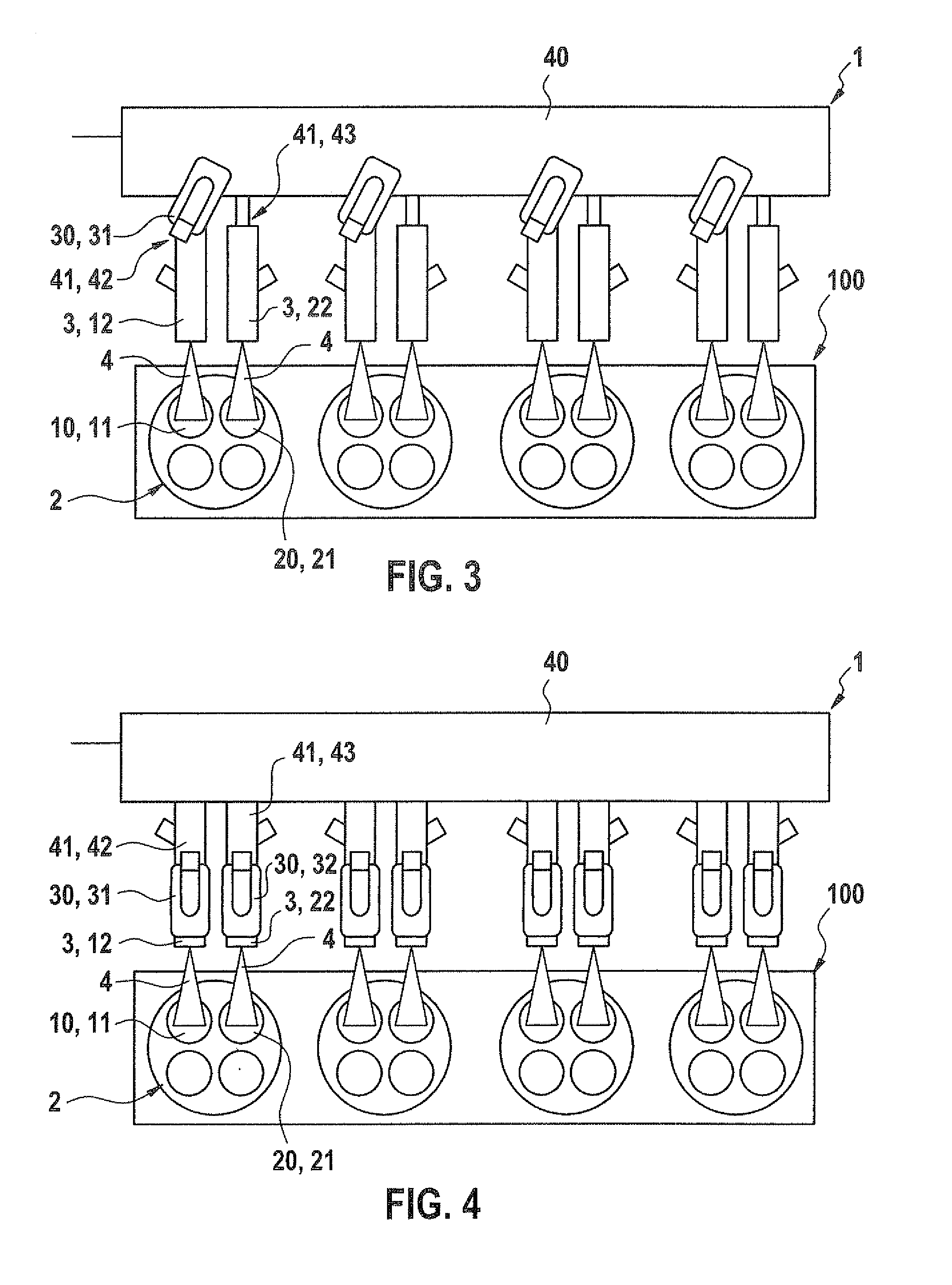
[0031]FIG. 1 shows a schematic view of an injection device 1 and of an internal combustion engine 100 according to a first specific embodiment of the present invention, the depicted internal combustion engine 100 having, as an example, four cylinders. Each of the four cylinders includes a combustion chamber 2 in which a piston moves. The wall of each combustion chamber 2 has a respective first inlet opening 10 and second inlet opening 20 through which an air-fuel mixture is suctioned into combustion chamber 2. Each combustion chamber 2 has, in addition, outlet openings through which the raw exhaust gases of the combusted air-fuel mixture are ejected from combustion chambers 2. Each of the cylinders has in addition a first inlet valve 11 that is provided in order to close respective first inlet opening 10, and a seco...


PUM


Abstract

An injection device for an internal combustion engine is proposed having at least one injection valve system for injecting fuel into an intake manifold of the internal combustion engine and at least one heating device for pre-heating fuel injected by the injection valve system, the injection valve system including a first injection valve for injecting fuel in the direction of a first inlet opening of a combustion chamber of the internal combustion engine and a separate, second injection valve for injecting fuel in the direction of a second inlet opening of the combustion chamber.

Description

RELATED APPLICATION INFORMATION[0001]The present application claims priority to and the benefit of German patent application no. 10 2011 007 327.2, which was filed in Germany on Apr. 13, 2011, the disclosure of which is incorporated herein by reference.FIELD OF THE INVENTION[0002]The present invention is based on an injection device.BACKGROUND INFORMATION[0003]Such injection devices for injecting fuel for internal combustion engines are believed to be generally understood. For example, DE 2 158 117 A1 an internal combustion discusses a throttle regulation in which fuel is injected by an injection device into the intake manifold leading into a combustion chamber of the internal combustion engine, the fuel being heated by an electric fuel heater before the injection in order to improve the evaporation of the fuel after the injection. This is an Otto engine having intake manifold injection, operated with a fuel based on gasoline.[0004]In addition, it is believed to be understood to ope...

Claims


Application Information

Patent Timeline
Patent Type & Authority Applications(United States)
IPC IPC(8): F02M53/06
CPCF02D19/0647F02D19/0692F02D19/084F02M31/125F02D41/3094Y02T10/126F02M69/044F02D41/062Y02T10/36Y02T10/12Y02T10/30
Inventor WINDBERGS, THORGUTSCHER, ANDREASPOSSELT, ANDREASLORENZ, MARKO
Owner ROBERT BOSCH GMBH
Learn More