
Pipe Repair Device

a pipe and pipe coupling technology, applied in the direction of pipes/joints/fittings, mechanical devices, pipe elements, etc., can solve the problems of leakage and loss of pressure of pipe couplings, air pressure, etc., and achieve the effect of being more resistant to degradation

Inactive Publication Date: 2012-11-08
KERR STEPHEN A +1
View PDF5 Cites 7 Cited by
  • Summary
  • Abstract
  • Description
  • Claims
  • Application Information

AI Technical Summary

Benefits of technology

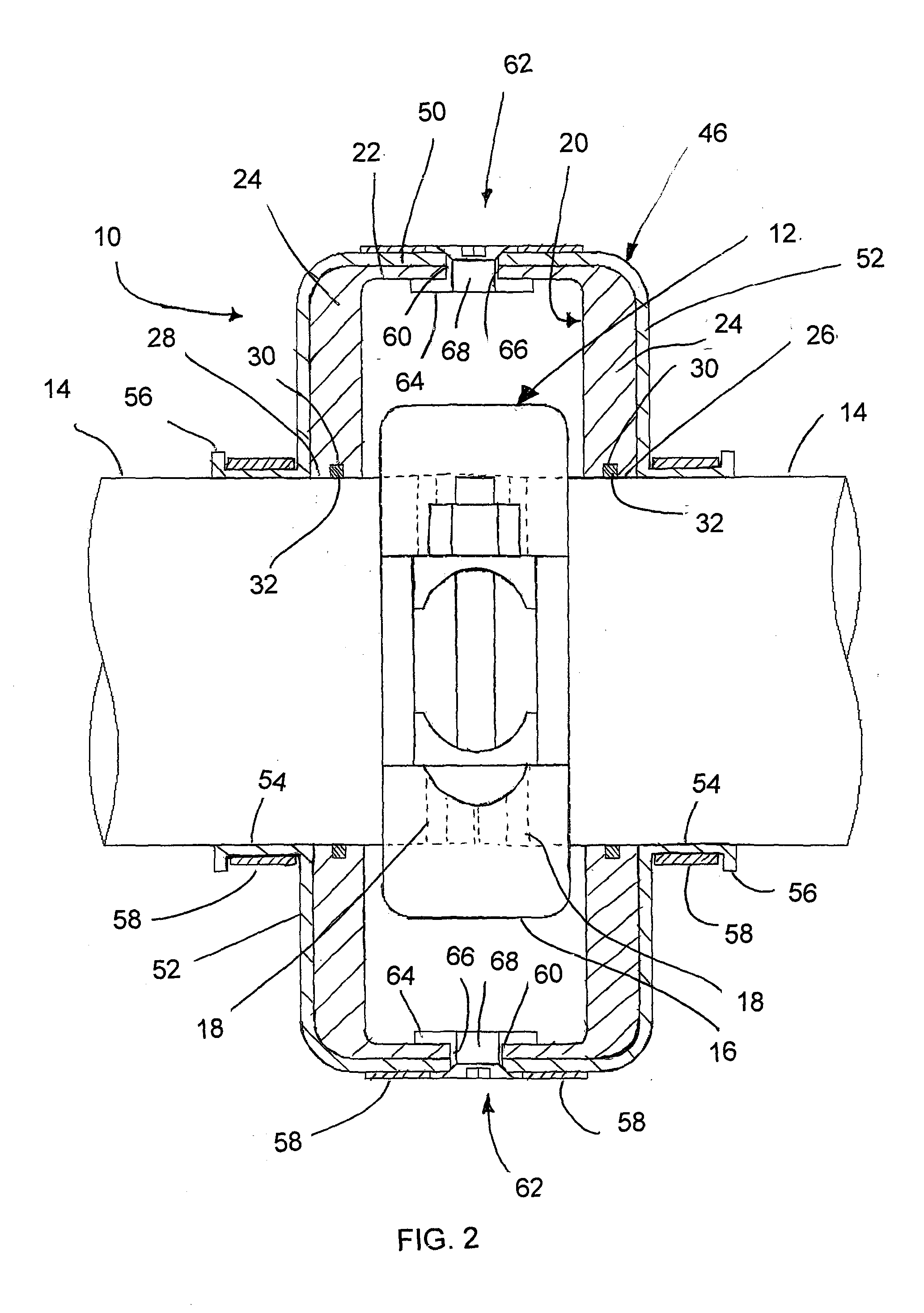
[0011]By providing a sealing member which comprises an envelope section to fully surround the leaking section such as a leaking pipe coupling between two sections of pipe, a large amount of sealing material is provided which is more resistant to degradation in corrosive environments such as air pressure systems in a mine. Furthermore, by providing a unitary envelope section, a minimum number of sealing surfaces are required to maintain a proper seal about the leaking section as there is only a single sealing interface between the sealing member and the pipe and no additional sealing interface is required between the sealing member and a surrounding clamp body as required in the prior art. Use of an extra housing surrounding the sealing member provides strength to the resilient material forming the sealing member but is not required to be relied upon for proper sealing of the leaking section in the pipe.

Problems solved by technology

High pressure air systems, for example the type used in mines and the like, commonly have many pipes distributed to different areas of the system involving many pipe couplings where there is a potential for leakage and loss of pressure.
The small cross section of sealing material in the grooves has potential to deteriorate quickly in the corrosive environment of mines and the like so that the resulting pipe couplings leak and lose pressure.
The loss in air pressure must be overcompensated by pressurizing more air into the system which consumes costly operating resources.
Shutting down the air system however results in costly down time.
In the example of mines, the loss of productive time is more costly than the extra operating costs of overcompensating for leaks in the air pressure system.
Failure of the seal can occur either at the interface of the sealing member with the pipe, or at the interface of the sealing member with the rigid clamp body surrounding the pipe so that there is a high probability of failure.
Also the sealing material is prone to quick degradation in corrosive environments when provided in a small cross section between a clamped body and a pipe.

Method used


Image

  • Pipe Repair Device
  • Pipe Repair Device
  • Pipe Repair Device

Examples


first embodiment

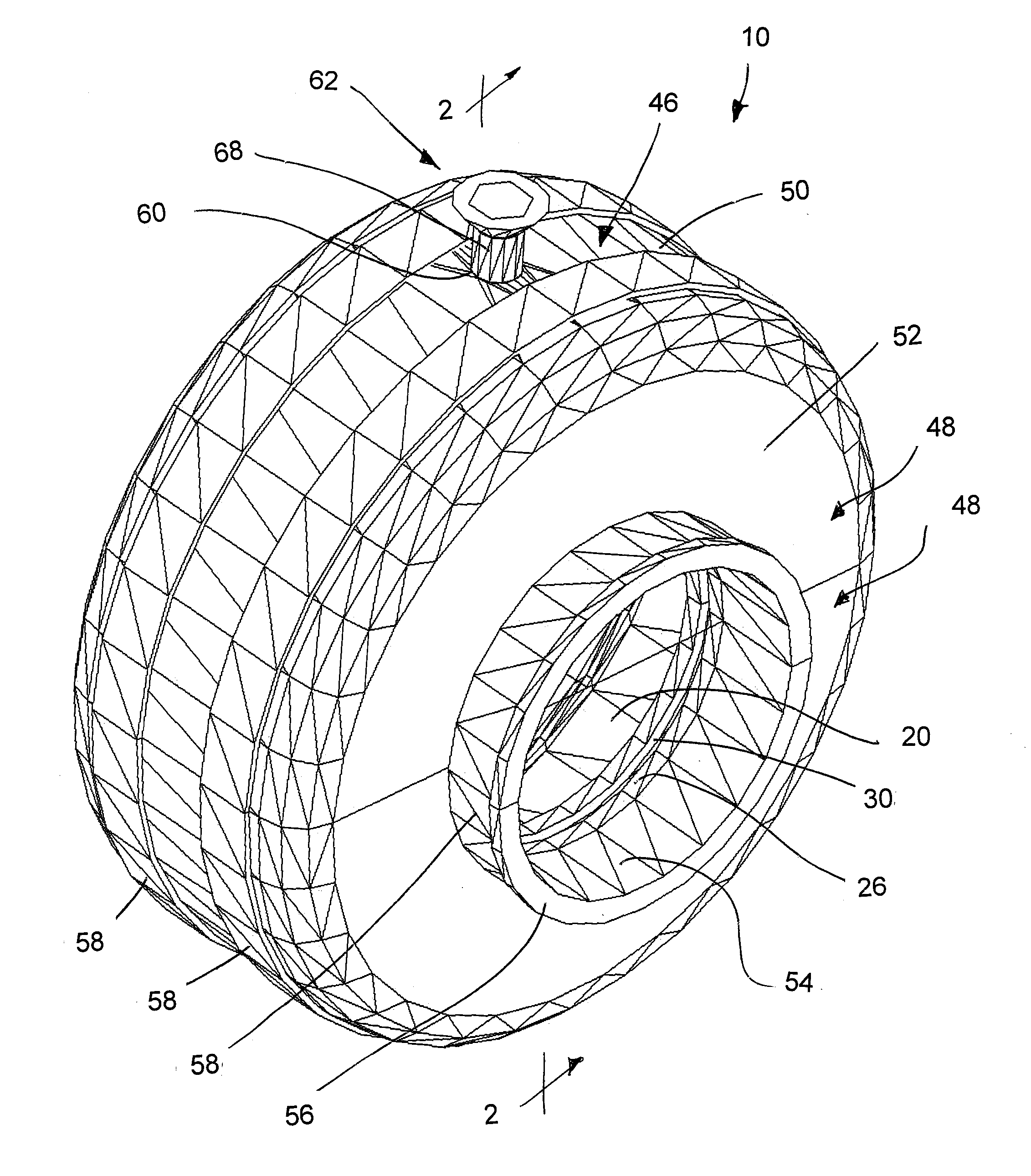
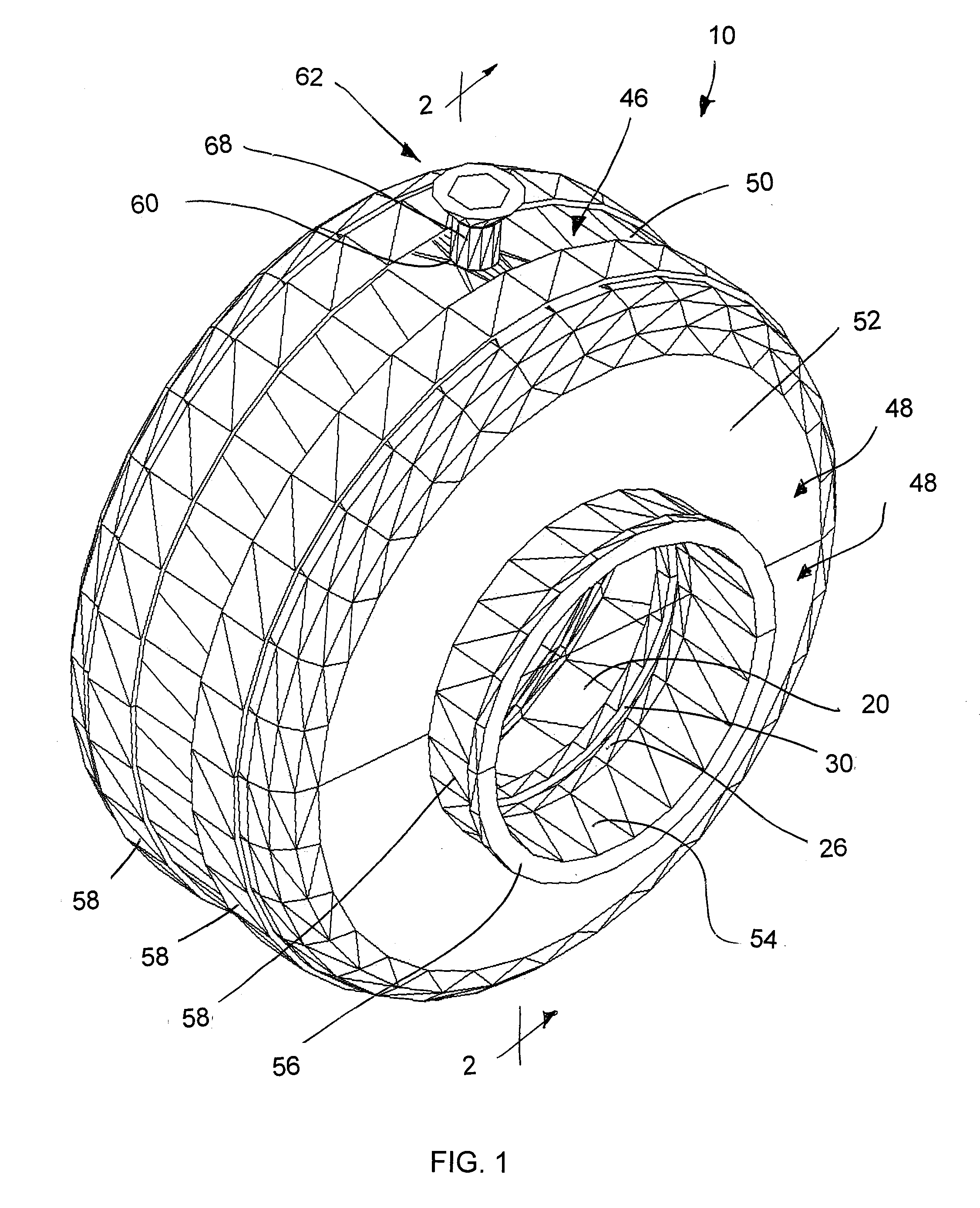
[0051]The pipe repair device 10 primarily comprises a sealing member 20 which comprises a unitary member of resilient material throughout which is molded integrally as a single seamless member. The resilient material according to the preferred embodiment comprises nitrile rubber; however other resilient materials which resist degradation when in contact with oil from compressed air lines would be suitable.

[0052]The sealing member 20 integrally comprises an outer wall 22 and two end walls 24 seamlessly joined therewith. The outer wall 22 is generally cylindrical in shape to extend a full circumference about the pipe coupling of the pipe by having an inner diameter which is larger than the diameter of the coupling to be spaced radially outward therefrom. The outer wall similarly extends in the axial direction of the pipe a distance which is only slightly greater and near to the axial width of the pipe coupling.

[0053]The two end walls 24 are joined at opposing ends of the outer wall 2...

second embodiment

[0071]Turning now to the embodiment of FIGS. 8 through 10, the repair device 10 is substantially identical to the previous embodiment of FIGS. 1 through 7 as described above with the exception of the following features.

[0072]In the second embodiment, each of the two symmetrical portions 48 of the housing 46 is provided with a pair of fastener mounts 100 at diametrically opposed locations adjacent the seam. Each of the fastener mounts 100 comprises a rigid protrusion of material projecting outward from the end wall 52 in the axial direction of the housing. The fastener mounts are located adjacent to the seam between the two symmetrical portions 48 such that when the two symmetrical portions are brought together the fastener mounts of one portion 48 are aligned with and directly adjacent corresponding fastener mounts 100 of the opposing portion 48. Cooperating apertures through the fastener mounts permit fasteners to be fastened between the two symmetrical portions at diametrically op...


PUM


Abstract

A repair device for repairing a leaking section in a pipe includes a sealing member of resilient material which fully surrounds the leaking section. The sealing member includes first and second annular sealing faces arranged for sealing engagement with the pipe about a full circumference thereof on opposite sides of the leaking section, and an envelope section fully spanning between the first and second annular sealing faces. The envelope section, the first annular sealing face, and the second annular sealing face are formed of resilient sealing material integrally joined with one another A rigid housing surrounds the sealing member and a clamp compresses the sealing member between the rigid housing and the leaking section of the pipe about the full circumference.

Description

[0001]This application claims priority to U.S. provisional application Ser. No. 61 / 293,428, filed Jan. 8, 2010.FIELD OF THE INVENTION[0002]The present invention relates to a repair device arranged to be clamped onto a pipe to repair a leak in the pipe, and more particularly, the present invention relates to a pipe repair device which is arranged to be clamped over a pipe coupling in a pipe in a high pressure air delivery system to repair a leak in the pipe coupling.BACKGROUND[0003]High pressure air systems, for example the type used in mines and the like, commonly have many pipes distributed to different areas of the system involving many pipe couplings where there is a potential for leakage and loss of pressure. A typical pipe coupling joins two pipe ends which have annular grooves formed therein to receive respective annular sealing members therein. The pipe coupling comprises a metal body arranged to be clamped over the pipe ends and the sealing members received in the grooves th...

Claims


Application Information

Patent Timeline
Patent Type & Authority Applications(United States)
IPC IPC(8): F16L55/18
CPCF16L55/172
Inventor KERR, STEPHEN A.HUBER, CAMERON G.
Owner KERR STEPHEN A
Learn More