User interfaces for designing objects

a user interface and object technology, applied in static indicating devices, instruments, cad techniques, etc., can solve the problems of reducing the degree of control of one designer on the design, increasing the cost of computing hardware required for faster image rendering, and affecting so as to preserve any distinctive design features, preserve the aesthetics of objects, and increase the freedom of choi

Active Publication Date: 2012-11-08
EOS ELECTRO OPTICAL SYST
View PDF3 Cites 64 Cited by
  • Summary
  • Abstract
  • Description
  • Claims
  • Application Information

AI Technical Summary

Benefits of technology

[0041]According to another aspect of the present invention there is provided a graphical user interface (GUI) for use in modifying an object design representation, the GUI comprising a viewing window for viewing the object design representation, a control panel for enabling user variation of a plurality of different variables associated with the design representation, wherein each different variable has an associated user operable graphical device the manipulation of which enables the displayed design representation to change in real time showing the effect of the change in value of the design variable on the design representation.
[0042]Preferably, each of the graphical devices have user adjustable features to set the range of variation of the design variable. The GUI may be arranged to enable the user to lock the value of the selected design variable. The GUI may be arranged to enable the user to select points of the design representation which are to form a subgroup of the whole design on which user manipulations can be carried out using the control panel. The GUI may be arranged to enable selection of a plurality of subgroups and for the user to lock at least some of the subgroups from any further variation. The control pane

Problems solved by technology

Thus, there is no ability for one designer to have a greater degree of control on the design than the other.
The effect of this large-power requirement is th

Method used


Image

  • User interfaces for designing objects
  • User interfaces for designing objects
  • User interfaces for designing objects

Examples


Embodiment Construction

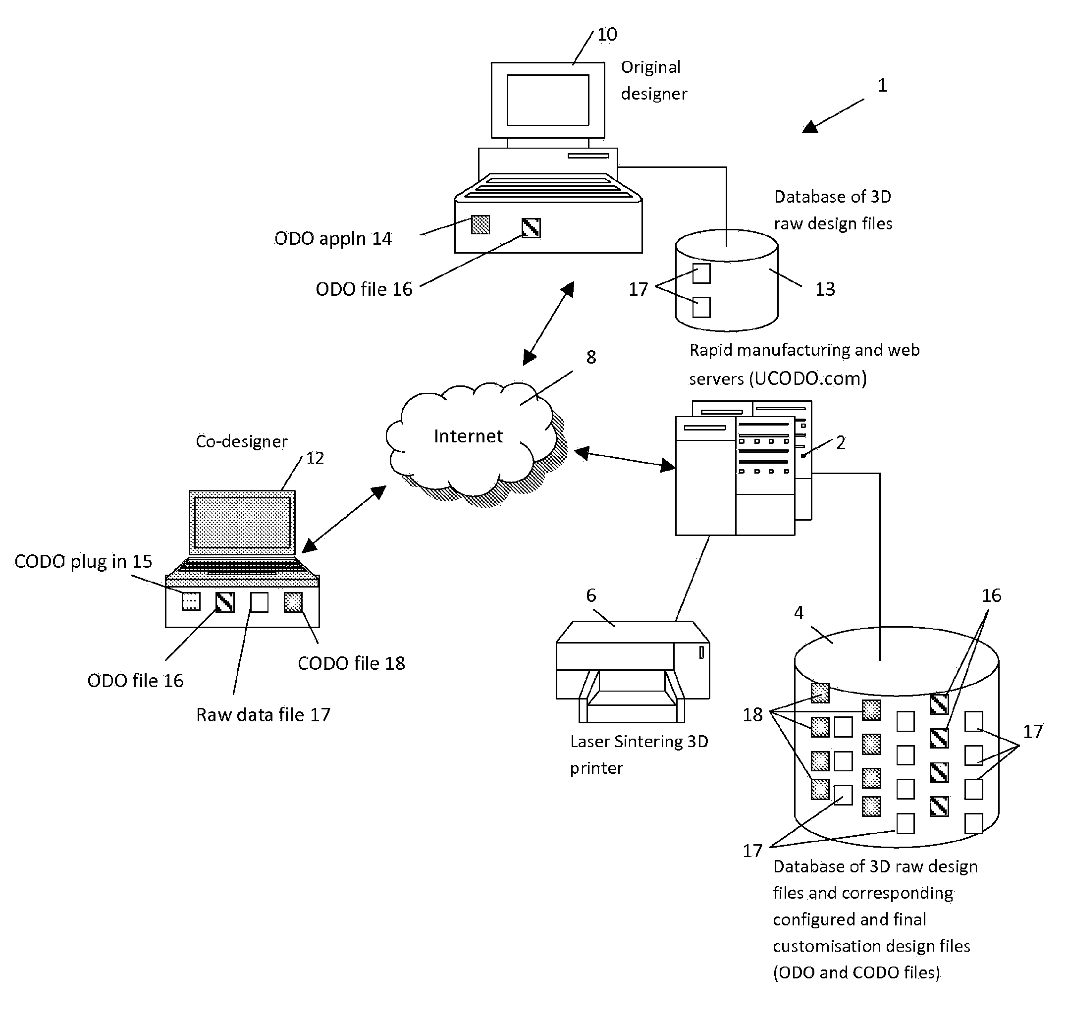
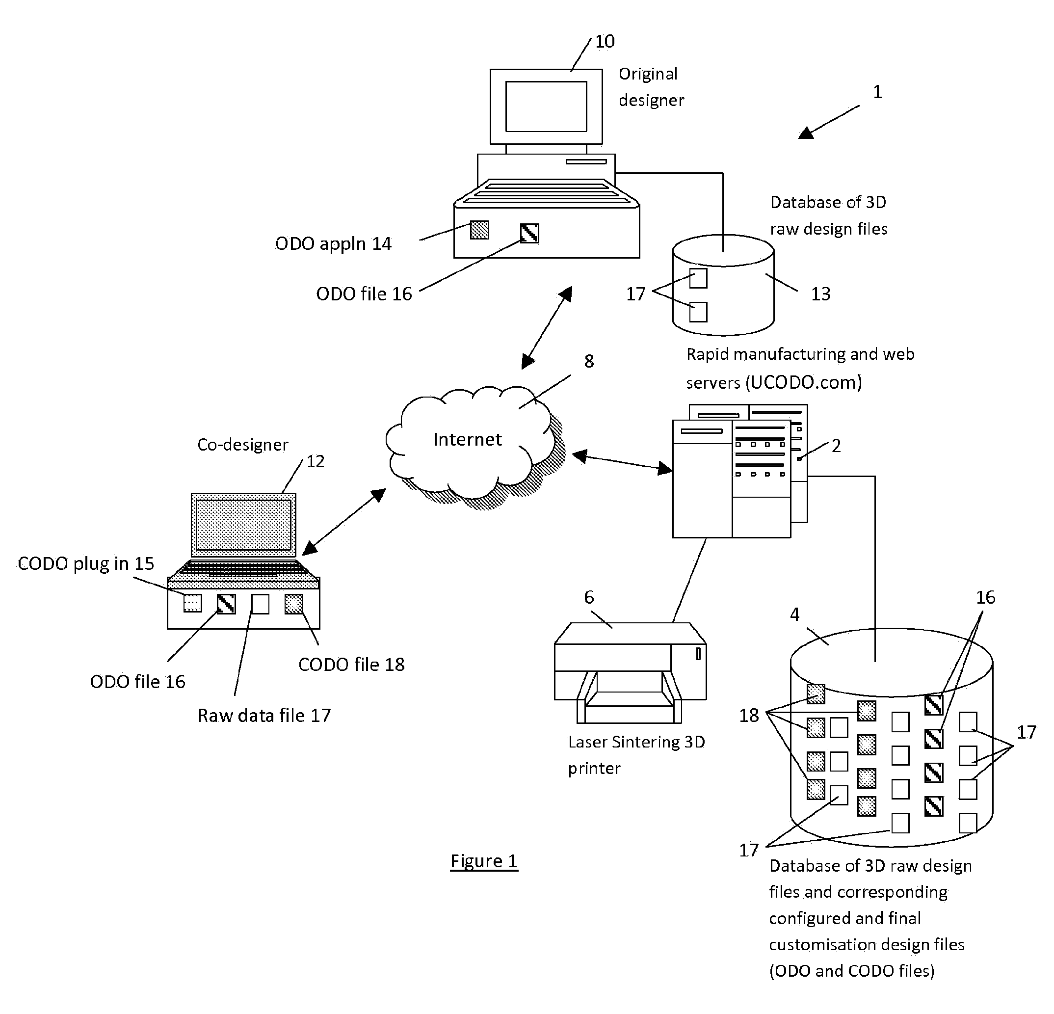
[0076]The present embodiment is made possible by the existence of rapid manufacturing and laser sintering technologies. There are essentially two stages to the process, the first being creation of a 3D design of the desired object and the second is the use of the design in manufacturing the object and providing that to the customer. The first stage involves creation by an original designer of a constrained design from a raw design data and thereafter the creation of a finalised design by a co-designer. This second stage is a printing process of the finalised design using layer-based manufacturing, using types of plastics, metals or composite metals in powder form. All manufacturing systems of this type comprise a combination of a computer CAD system with a laser sintering machine (or 3D printer) to perform the fabrication of a layer under computer control.

[0077]An embodiment of the present invention is implemented as a rapid manufacturing system providing a web-based service. Referr...


PUM


Abstract

A collaborative method of generating a design representation of an object between a first user and a second user is described. The method comprises: designating, at a first user terminal, a set of design object variables relating to different aspects of the design representation; specifying, at the first user terminal, constraints for the set of design object variables, the constraints comprising a range of first user designated values for each of the designated object variables of the set; receiving at a second user terminal, the set of design object variables, the constraints for the set and the design representation via a communication network; enabling, at the second user terminal, manipulation of the design object representation, the enabling step comprising enabling selection of a particular value of at least one of the designated object variables only within the constrained value range specified by the first user; and presenting on the second user terminal a graphical representation of the design object representation as specified by the second user selection.

Description

FIELD OF THE INVENTION[0001]The present invention concerns improvements relating to user interfaces for designing objects, and more specifically though not exclusively to an improved process for the cooperative design of industrially manufactured objects. The present invention also concerns enhanced new ways of image manipulation for the purposes of altering industrial designs and controlling such alteration to preserve the function of the article being designed.BACKGROUND OF THE INVENTION[0002]Current Computer-Aided Design software packages range from two-dimensional (2D) vector-based drafting systems to three-dimensional (3D) solid and surface modelling systems. Existing 3D Computer Aided Design (CAD) packages (such as AutoCAD and QCAD) are available for designing industrial objects of manufacture. Typically, a designer familiar with such packages uses them to design a particular industrial object for mass production. Modifications can be made during the design process and these a...

Claims


Application Information

Patent Timeline
IPC IPC(8): G09G5/00
CPCG06F17/50G06T19/00G06F2217/06G06F2217/04B33Y50/00G06F2111/02G06F2111/04G06F30/00G06F3/04815G06F3/04817G06F3/04845
Inventor MAHDAVI, SIAVASH HAROUNASHUACH, ASSADE CORDES, NICOLAS
Owner EOS ELECTRO OPTICAL SYST
Why Eureka
Try Eureka