Apparatuses, systems, and methods for determining location of a mobile device(s) in a distributed antenna system(s)

Active Publication Date: 2012-11-08
CORNING OPTICAL COMM LLC
View PDF14 Cites 117 Cited by
  • Summary
  • Abstract
  • Description
  • Claims
  • Application Information

AI Technical Summary

Benefits of technology

[0012]In another embodiment, a computer-readable medium having stored thereon computer-executable instructions to cause an LPU configured to determine the location of at least one client device wirelessly communicating in a distributed antenna system is provided. The computer-executable instructions cause the LPU to receive uplink RF signals communicated by at least one client device wirelessly communicating to a plurality of antenna units. The computer-executable instructions cause the LPU to determine the signal stre

Problems solved by technology

For example, transmission and reception of RF signals are often blocked inside high buildings due to thick steel, concrete floors and walls.
Similar problems can be found in other areas such as airports, shopping malls or tunnels, etc.
Otherwise, wireless reception may be poor or not possible for wireless communication clients located inside the building.
While extending the remote antenna units to locations in the building can provide seamless wireless coverage to wireles

Method used


Image

  • Apparatuses, systems, and methods for determining location of a mobile device(s) in a distributed antenna system(s)
  • Apparatuses, systems, and methods for determining location of a mobile device(s) in a distributed antenna system(s)
  • Apparatuses, systems, and methods for determining location of a mobile device(s) in a distributed antenna system(s)

Examples


Embodiment Construction

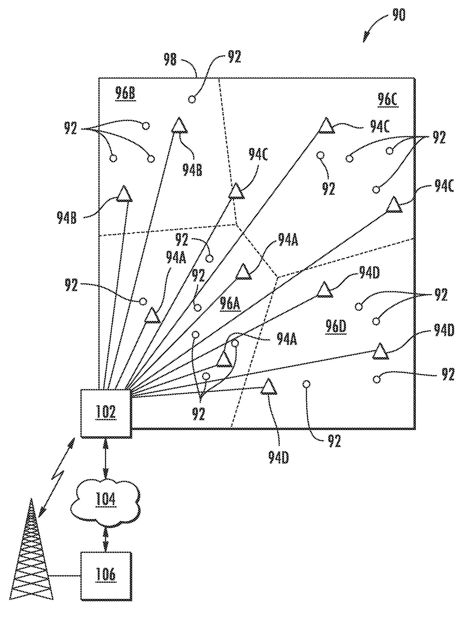
[0009]Embodiments disclosed in the detailed description include distributed antenna apparatuses, systems, methods, and computer-readable mediums to provide location information regarding client devices communicating with remote antenna units in a distributed antenna system. The location information can be used to determine the location of the client devices relative to the remote antenna unit(s) in which the client devices are communicating. In this scenario, the client devices would be known to be within communication range of the remote antenna units. This information can be used to determine or provide a more precise area of location of the client devices. The distributed antenna components and systems, and related methods disclosed herein may be well suited for indoor environments where other methods of providing and / or determining the location of client devices may be obstructed or not possible due to the indoor environment.

[0010]In this regard, in certain embodiments disclosed...


PUM


Abstract

Distributed antenna systems provide location information regarding client devices communicating with remote antenna units (RAU) in a service area. The location information can be used to determine the location of client devices relative to the RAU(s) with which the client devices are communicating. A location processing unit (LPU) is configured to provide location information for client devices. The LPU includes a control system configured to receive uplink radio frequency (RF) signals communicated by a client device wirelessly communicating to a plurality of RAUs. The control system determines location information for a client device based on which RAU receives the strongest signal from the client device.

Description

RELATED APPLICATIONS[0001]The present application is a continuation of International Application No. PCT / US2010 / 044884, filed Aug. 9, 2010, the entire content of which is relied upon and incorporated by reference herein.BACKGROUND[0002]1. Field of the Disclosure[0003]The technology of the disclosure relates to distributed antenna and communications systems, including mobile distributed telecommunication systems and networks, for distributing communications signals to remote antenna units. The distributed antenna and communications systems can include any type of media, including but not limited to optical fiber to provide an optical fiber-based distributed antenna system.[0004]2. Technical Background[0005]Wireless communication is rapidly growing, with ever-increasing demands for high-speed mobile data communication. As an example, so-called “wireless fidelity” or “WiFi” systems and wireless local area networks (WLANs) are being deployed in many different types of areas (e.g., coffe...

Claims


Application Information

Patent Timeline
IPC IPC(8): H04W24/00H04W72/04H04J3/14H04W4/021H04W4/33H04W4/40H04W4/60
CPCH04W16/20H04W88/085H04W64/00H04W4/021H04W4/023H04W56/0015H04W4/33H04B17/318H04B7/0413H04B10/25752H04W4/40H04W4/60
Inventor SAUER, MICHAEL
Owner CORNING OPTICAL COMM LLC
Why Eureka
Try Eureka