Sensor system

Inactive Publication Date: 2012-11-08
KONINKLIJKE PHILIPS ELECTRONICS NV
View PDF6 Cites 34 Cited by
  • Summary
  • Abstract
  • Description
  • Claims
  • Application Information

AI Technical Summary

Benefits of technology

[0016]It would be desirable to provide an improved sensor system with increased interpretation possibilities. It

Problems solved by technology

A concern of current sensor systems is that due to the many different situations that may arise during use of the sensor system, interpretation of the sensor data obtained by the sensor system is not detailed enough and/or the sensor data is distorted which reduces the possibility to gain useful information from the sensor data.
However, this means that information may be obtained indicating whether a baby or young child is lying on its side, but detailed information whether the baby or yo

Method used


Image

  • Sensor system
  • Sensor system
  • Sensor system

Examples


Embodiment Construction

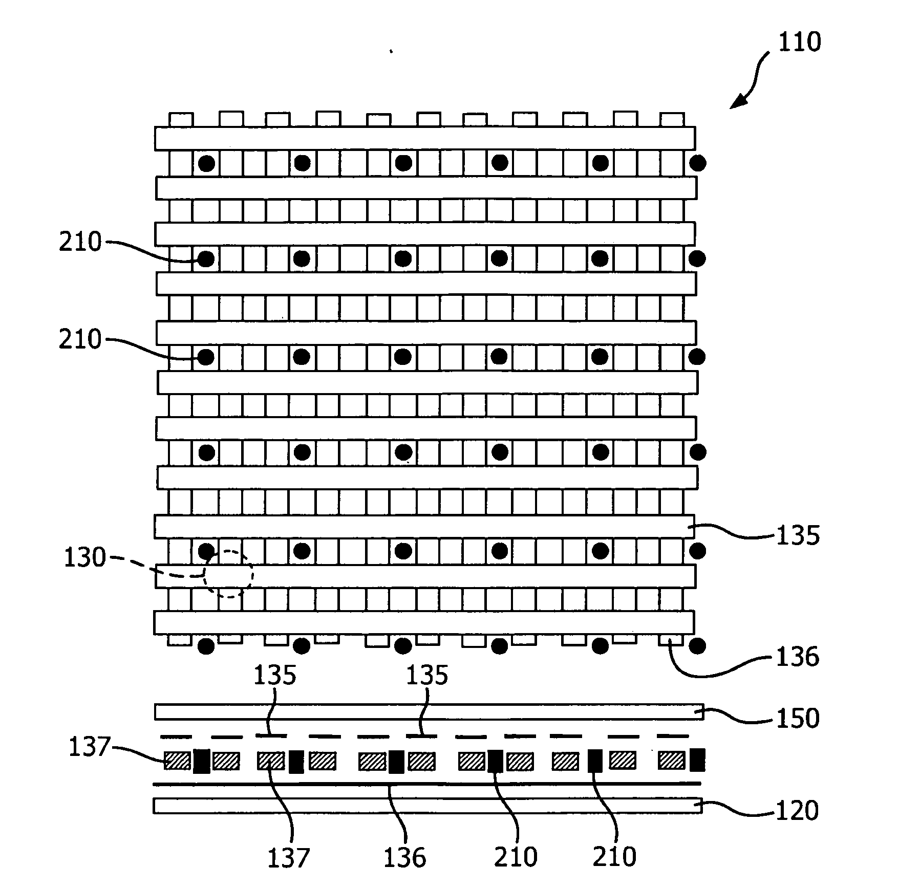
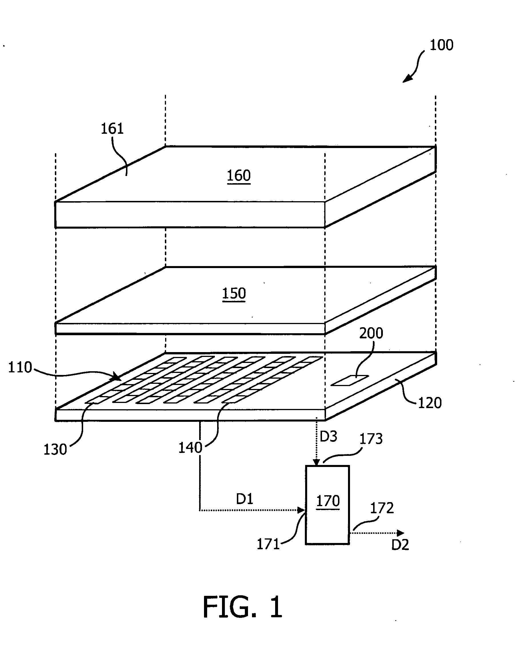
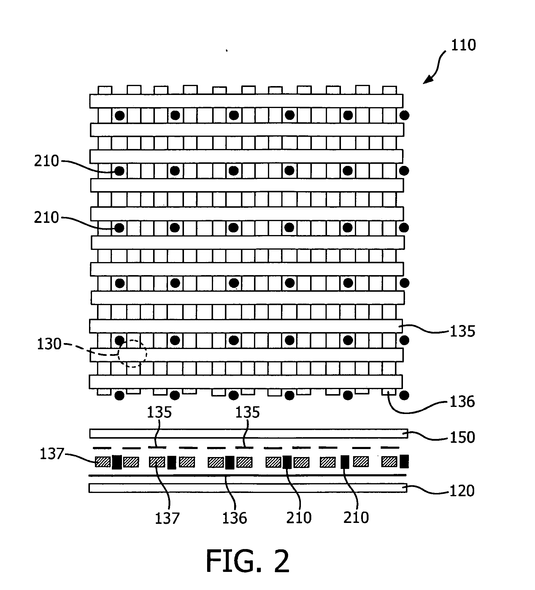
[0069]FIG. 1 depicts a sensor system 100 according to an embodiment of the invention. FIG. 1 is an exploded schematic view of the sensor system 100. The sensor system 100 comprises a sensor array 110. The sensor array 110 comprises a first substrate layer 120 and a plurality of individual first sensor elements 130, in this case in the form of pressure sensitive elements. The first sensor elements 130 are arranged on the first substrate layer 120 to measure pressure exerted on the sensor array by an object or living subject (not shown) which may be positioned on a support surface 161. As can be seen, the first sensor elements 130 in the example shown define a substantially flat sensor plane 140.

[0070]The first sensor elements 130, in the example of FIG. 1, are covered by a second substrate layer 150 of similar dimensions as the first substrate layer 120. The provision'of the second substrate layer 150 is not essential, but may be convenient for protecting the sensor elements 130.

[007...


PUM


Abstract

The invention relates to a sensor system comprising a sensor array, the sensor array comprising a substrate layer and a plurality of individual first sensor elements for measuring a desired parameter, which first sensor elements are arranged on said substrate layer and define a sensor plane, wherein the sensor array further comprises one or more second sensor elements for measuring a further desired parameter, and wherein the sensor system is configured to process sensor data from the first sensor elements in dependency of sensor data from the one or more second sensor elements.

Description

FIELD OF THE INVENTION[0001]The invention relates to the field of sensor systems, and more specifically to flexible sensor systems used for monitoring a person, i.e. a living subject, in particular a young child or patient, positioned on the sensor system. The invention further relates to a method for processing sensor data received from a sensor system.BACKGROUND OF THE INVENTION[0002]Sensor systems are widely known and widely used in an almost unlimited number of applications and application areas. One particular type of sensor system comprises a so-called Flexible Large-Area Sensor Carrier or FLASC. Such a sensor system is for example known from Tekscan, which produces the clinical BPMS™ system (Body Pressure Measurement System). Typically such a system comprises flexible polyester sheets on which electrically conductive electrodes are positioned such that the electrodes face each other. The electrodes are arranged in a patterned manner. The known BPMS™ system is a pressure sensi...

Claims


Application Information

Patent Timeline
IPC IPC(8): G06F15/00G01K7/00G01P15/00G01D18/00G06F19/00
CPCA61B5/01A61B5/103A61B5/11A61B5/113A61B5/4818A61B2562/046A61B5/721A61B2503/06A61B2560/0252A61B2562/0219A61B2562/0247A61B5/6892
Inventor BRUEKERS, ALPHONS ANTONIUS MARIA LAMBERTUSBREEBAART, DIRK JEROENBOUGHORBEL, SABRI
Owner KONINKLIJKE PHILIPS ELECTRONICS NV
Why Eureka
Try Eureka