

Hardware stimulus engine for memory receive and transmit signals
- Summary
- Abstract
- Description
- Claims
- Application Information
AI Technical Summary
Benefits of technology
Problems solved by technology
Method used
Image

Examples
Embodiment Construction
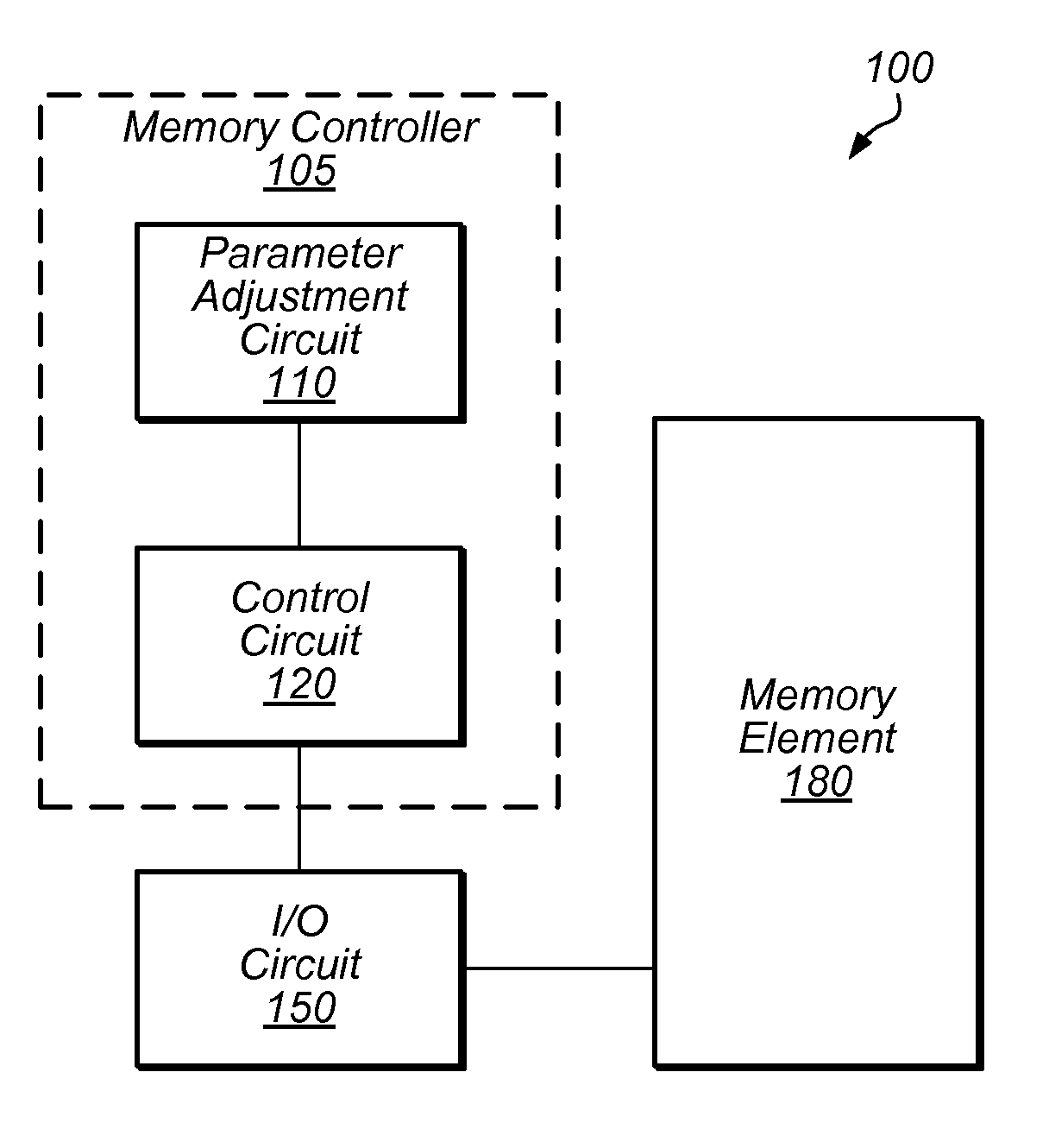
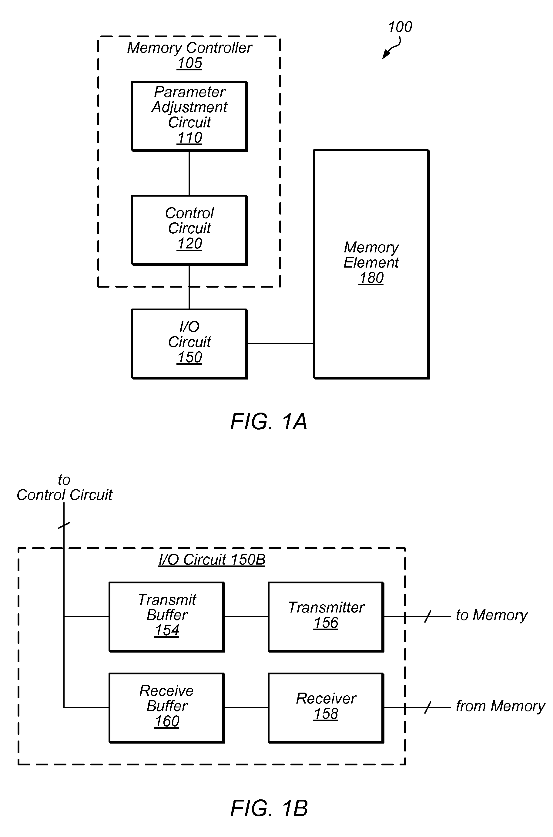
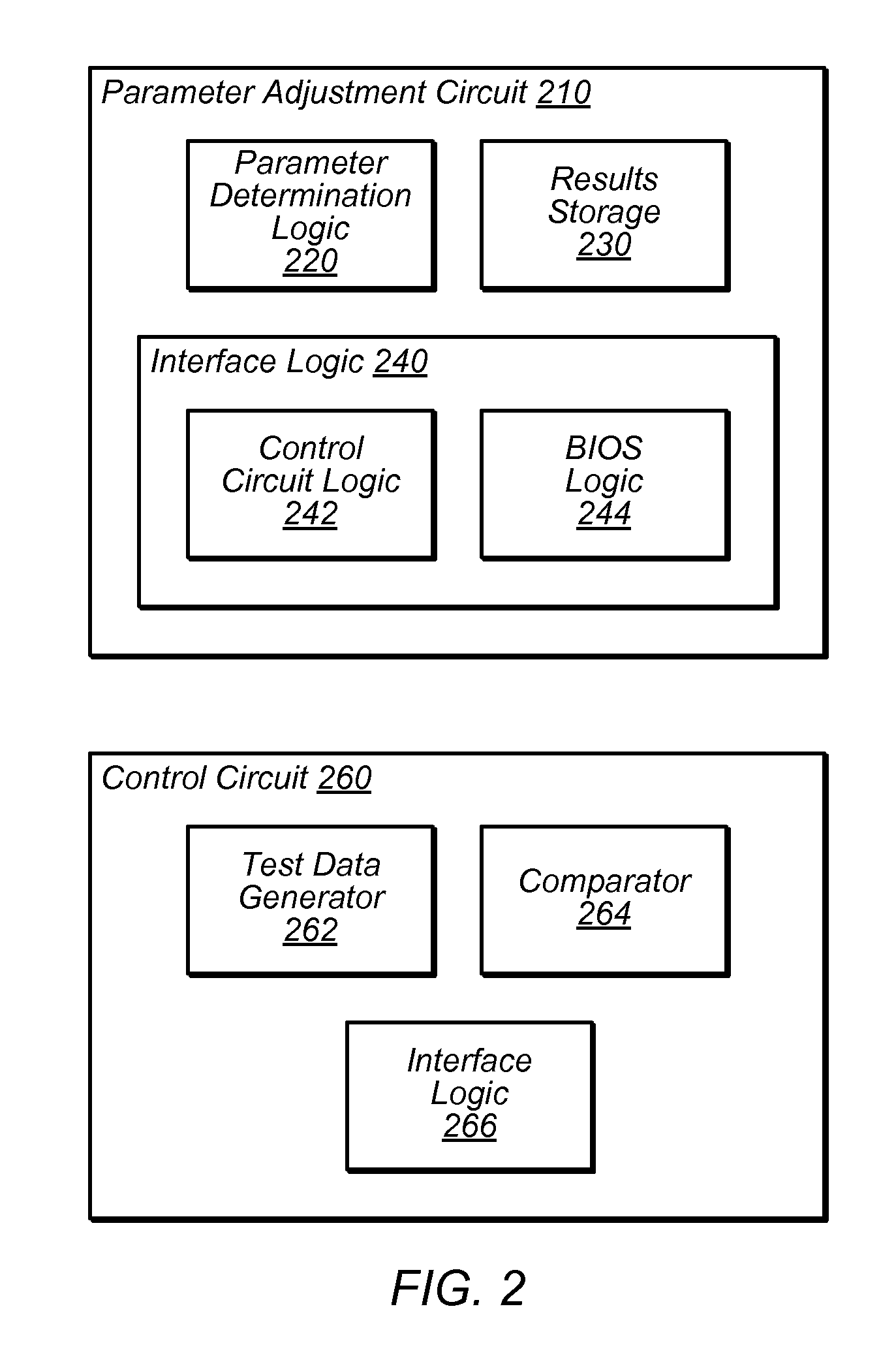
[0006]In one embodiment, a memory controller comprising a control circuit and a parameter adjustment circuit is disclosed. The control circuit is configured to perform a test of a memory element using one or more memory training parameters, and the parameter adjustment circuit is configured to receive an intermediate result of the test and adjust at least one of the one or more memory training parameters based on the intermediate result.
[0007]In another embodiment, a method is disclosed, comprising a memory controller performing a plurality of trials of a memory element, wherein an initial one of the plurality of trials uses a first value for a timing parameter, wherein subsequent ones of the plurality of trials each use a respectively different value for the timing parameter, and wherein the respectively different value is determined by the memory controller based on results of one or more previously performed ones of the plurality of trials of the memory element. The method also c...
PUM
 Abstract
Description
Claims
Application Information