

Lobed swirler
a swirler and lobe technology, applied in the field of lobed swirlers, can solve the problems of high nox emission levels and higher life cycle costs
Active Publication Date: 2012-11-15
ANSALDO ENERGIA SWITZERLAND AG
View PDF13 Cites 83 Cited by
- Summary
- Abstract
- Description
- Claims
- Application Information
AI Technical Summary
Problems solved by technology
As a result, there can arise high NOx emission levels and higher life cycle costs.
Method used
View moreImage
Smart ImageViewing Examples

Examples
exemplary embodiment 1
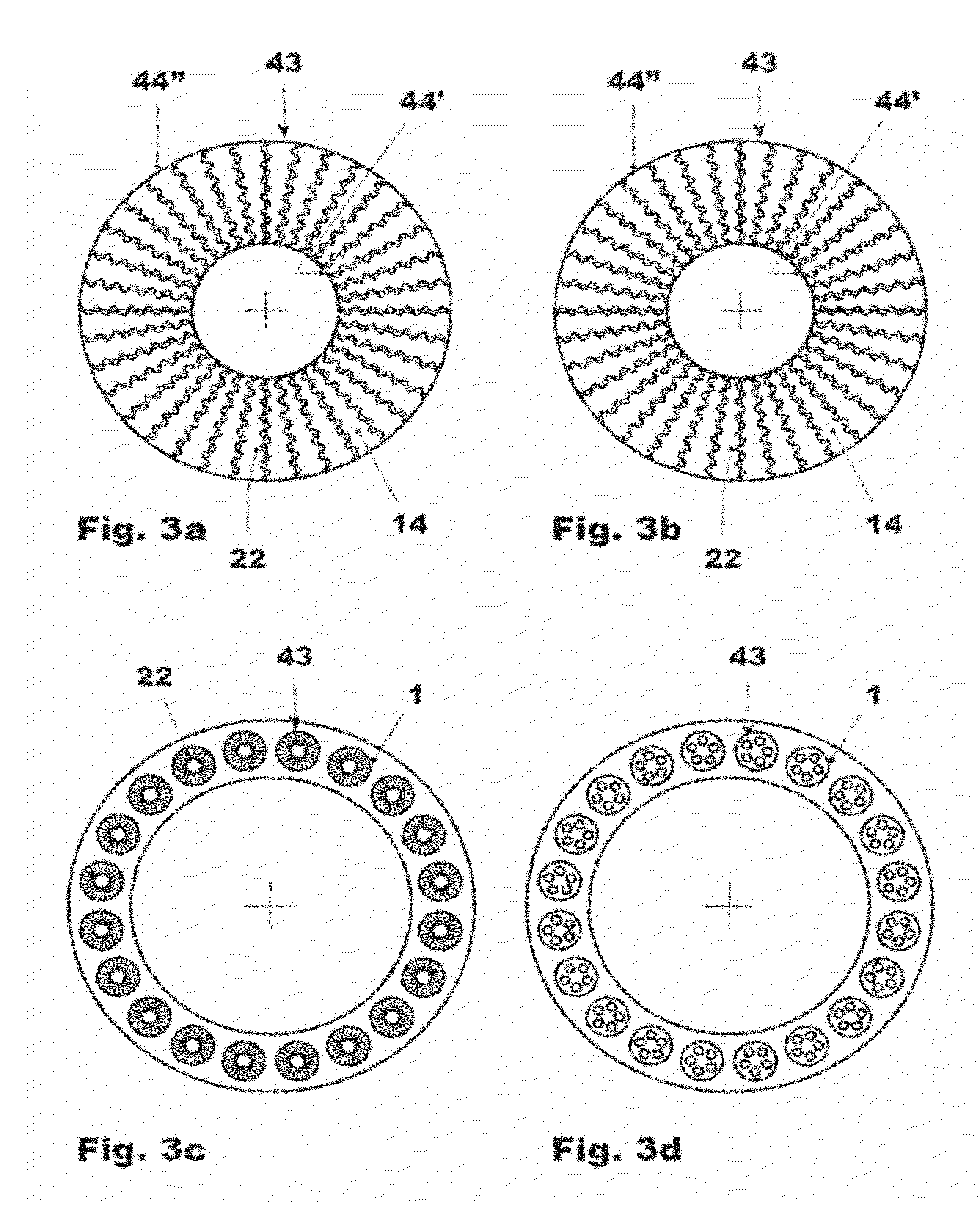
[0113]Staggering of lobes to eliminate vortex-vortex interactions. The vortex-vortex interactions can result in not effectively mixing the fuel air streams.
exemplary embodiment 2
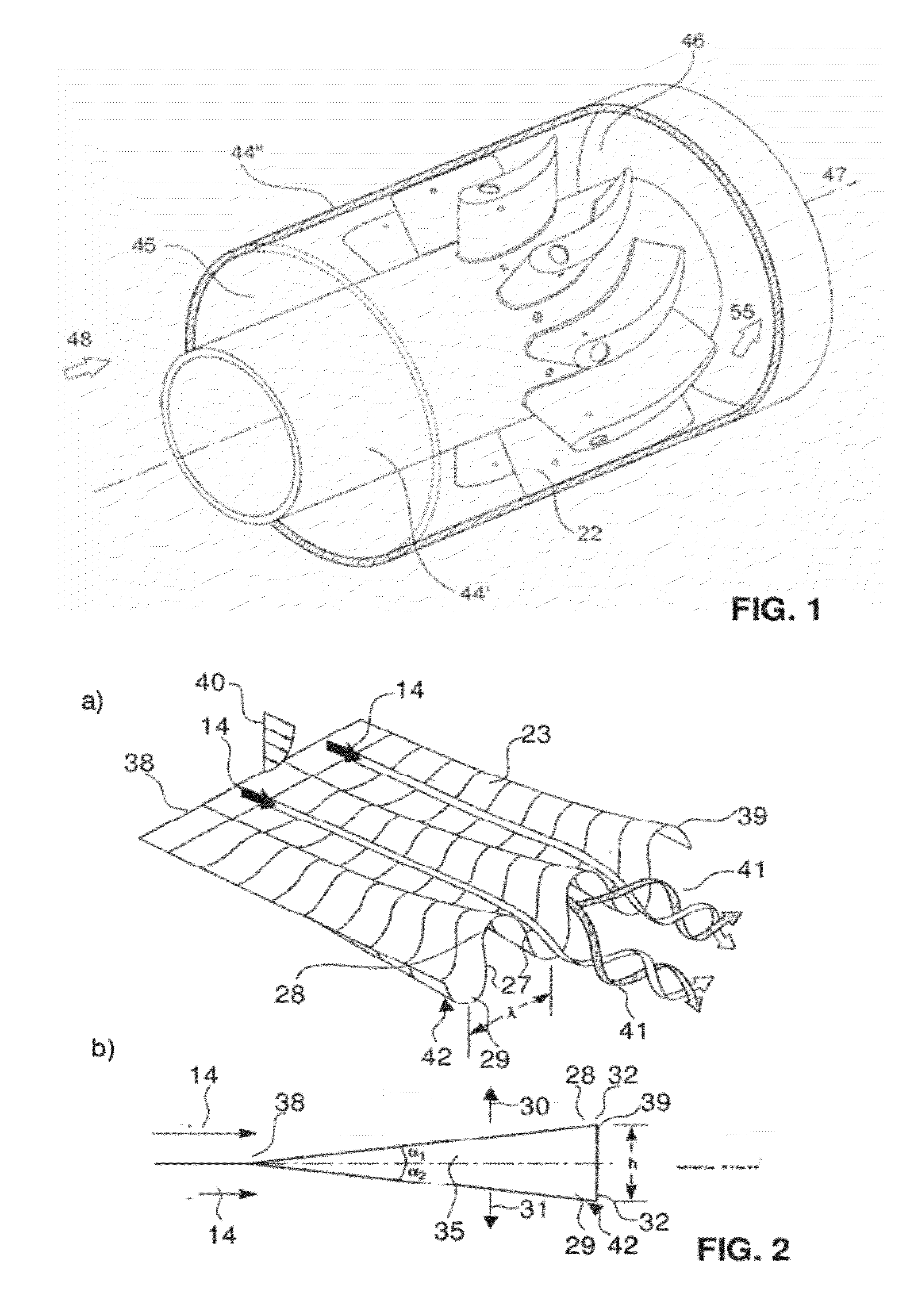
[0114]Careful placement and location of fuel injection on the lobes: Fuel jets can be placed in the areas of high shear regions in order to utilize the turbulent dissipation for mixing.
exemplary embodiment 3
[0115]Inclined fuel injection in the lobes: This can allow fuel to be injected in to the vortex cores.
Login to View More PUM
 Abstract
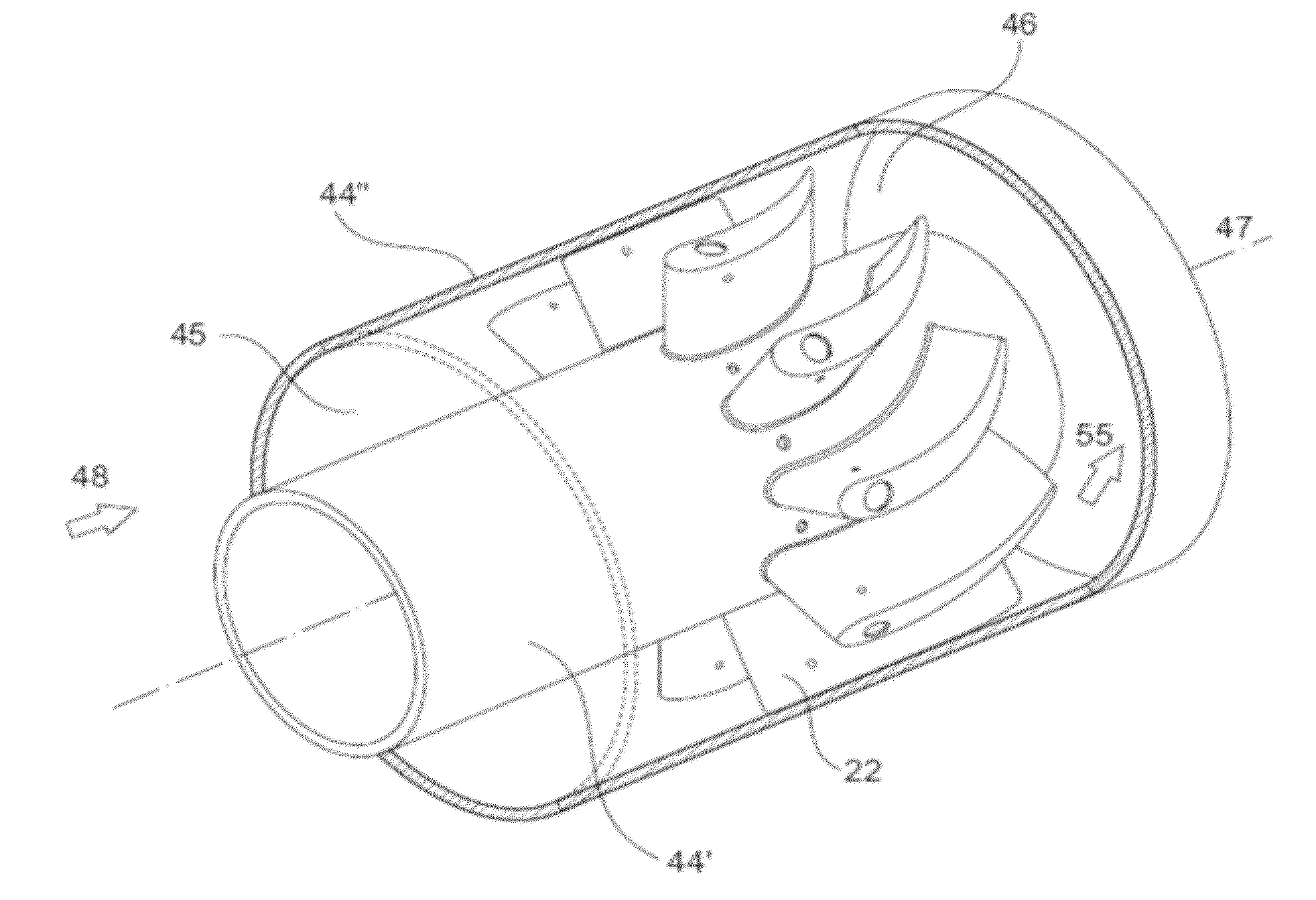
A swirler including an annular housing with limiting walls. At least two vanes are arranged in the annular housing including the sidewalls of the swirler. The leading edge area of each vane has a profile, which is oriented parallel to a main flow direction prevailing at the leading edge position, wherein the profiles of the vanes turn from the main flow direction prevailing at the leading edge position to impose a swirl on the flow, and wherein, with reference to a central plane of the vanes the trailing edges are provided with at least two lobes in opposite transverse directions. A burner for a combustion chamber of a gas turbine including such a swirler and at least one nozzle having its outlet orifice at or in a trailing edge of the vane and to a method of operation of such a burner.
Description
RELATED APPLICATION(S)[0001]This application claims priority under 35 U.S.C.§119 to European Patent Application No. 00794 / 11 filed in Switzerland on May 11, 2011, the entire content of which is hereby incorporated by reference in its entirety.FIELD[0002]The present disclosure relates to a lobed swirler, for example, to lobed swirlers for the introduction of at least one gaseous and / or liquid into a burner as well as a burner for a combustion chamber of a gas turbine including a lobed swirler.BACKGROUND INFORMATION[0003]Swirlers can be provided for mixing devices in various technical applications. Optimization of swirlers aims to reduce energy to obtain a specified degree of homogeneity. In continuous flow mixing, a pressure drop over a mixing device is a measure of energy. Further, the time and space to obtain the specified degree of homogeneity are useful parameters when evaluating mixing devices or mixing elements. Swirlers can be used for mixing of two continuous fluid streams.[0...
Claims
Login to View More Application Information
Patent Timeline
 IPC IPC(8): F23R3/14F15C1/16
CPCF23C7/004F23R3/14F23D2900/14021F23D2900/14004Y10T137/2087
InventorPOYYAPAKKAM, MADHAVAN NARASIMHANBIAGIOLI, FERNANDOSYED, KHAWARMAO, RONGHAIBERNERO, STEFANO
OwnerANSALDO ENERGIA SWITZERLAND AG