Thermal Power Boiler

a technology of thermal energy boiler and air channel, which is applied in the direction of regenerative heat exchangers, combustion processes, lighting and heating apparatus, etc., can solve the problems of complex design and assembly of other equipment and parts of the furnace, and achieve the effect of simple geometry, short air channel, and reduced pressure loss in the channel

Active Publication Date: 2012-11-15
AMEC FOSTER WHEELER ENERGIA
View PDF79 Cites 0 Cited by
  • Summary
  • Abstract
  • Description
  • Claims
  • Application Information

AI Technical Summary

Benefits of technology

[0023]According to a preferred embodiment of the present invention, the pre-heater for combustion air is arranged in such a way that the outlet connection for combustion air is at least partially, most preferably, complete, outside the area underneath the back pass. When the outlet connection for combustion air is outside the area underneath the back pass, the flow channel, or flow channels, of combustion air can be led to the furnace via a most advantageous route. It is not necessary to especially form extensions or special bends in the flow channel for combustion air leading to the furnace, so-called feed channels for combustion air, in order to pass the back pass or the flue gas channel. The shortness of the air channels and the simple geometry thereof diminish the pressure loss in the channels, whereby the power consumption of the blowers for combustion air diminishes or, alternatively, the cross section of the air channels can be diminished, thus,

Problems solved by technology

When the furnace of a large thermal power boiler, back pass and pre-heater for combustion air are arranged conventionally one after another, the channels connecting them to each other can become long, whereby the design and assembly thereof among the other equipment and parts related to the furnace is complicated.
A problem with such an arran

Method used


Image

  • Thermal Power Boiler
  • Thermal Power Boiler
  • Thermal Power Boiler

Examples


Embodiment Construction

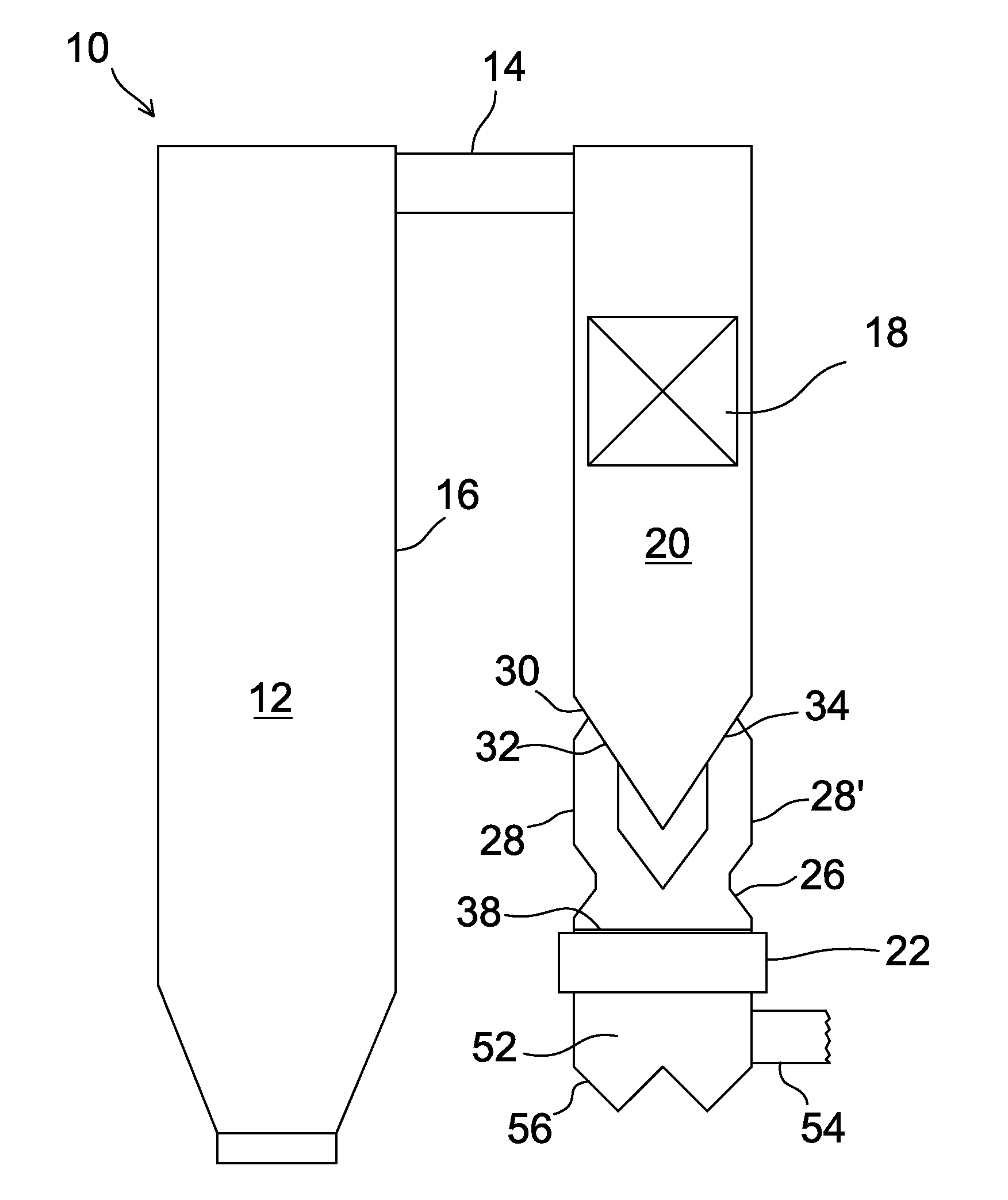
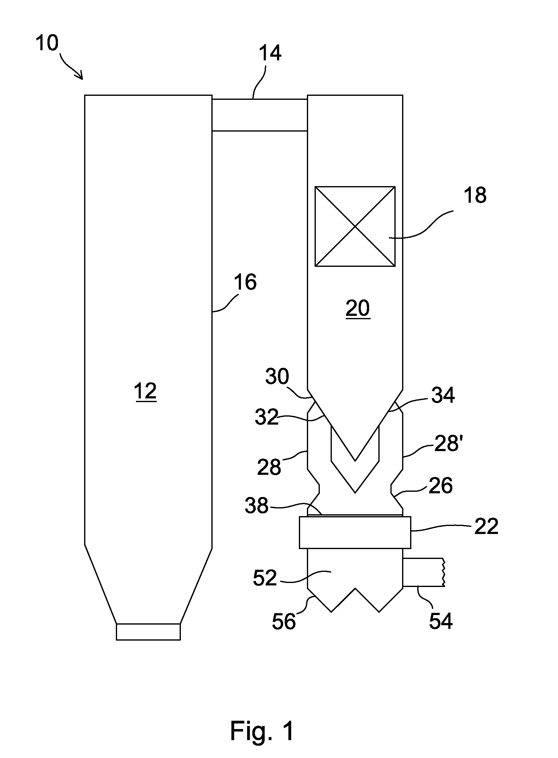
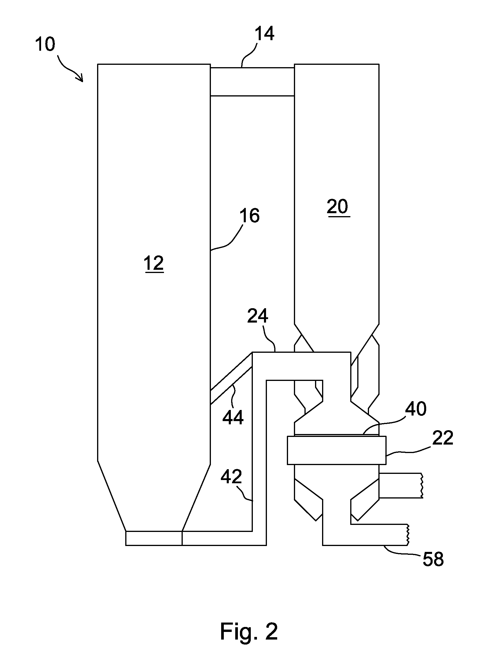
[0032]FIGS. 1-3 disclose an exemplary thermal power boiler 10 in accordance with the invention. The thermal power boiler 10 comprises a furnace 12 and a flue gas channel 14 connected to the furnace 12, which flue gas channel 14 conducts flue gas from the furnace 12 through a back pass 20, arranged on the side of a rear wall 16 of the furnace 12 and provided with heat exchange surfaces 18, and inlet channels 26, 26′ for flue gas to two parallel connected pre-heaters 22, 22′ for combustion air. The thermal power boiler 10 can be, for example, a large circulating fluidized bed boiler, the electrical capacity of which is more than 500 MWe, or a pulverized coal boiler.

[0033]FIG. 1 is a vertical cross section of the thermal power boiler 10 taken perpendicularly to the rear wall 16 of the furnace 12 at the inlet channel 26 for flue gas. FIG. 2 is a corresponding vertical cross section taken at the point at the flow channel 24 for combustion air. FIG. 3 is a vertical cross section in the di...


PUM


Abstract

A thermal power boiler includes a furnace having a rear wall, a flue gas channel connected to the furnace, the flue gas channel including a back pass arranged on the rear wall side of the furnace, and a pre-heater for combustion air provided with an inlet channel for flue gas, the upper portion of the inlet channel for flue gas being connected to the lower portion of the back pass, and a flow channel for combustion air arranged adjacent to the inlet channel for flue gas, leading pre-heated combustion air to the furnace. The inlet channel for flue gas includes two adjacent channel portions that are connected to opposite sides of the back pass.

Description

[0001]This application is a U.S. national stage application of PCT International Application No. PCT / FI2010 / 050371, filed May 7, 2010, published as PCT Publication No. WO 2010 / 128213 A2, and which claims priority from Finnish patent application number 20095519, filed May 8, 2009.FIELD OF THE INVENTION[0002]The present invention relates to a thermal power boiler comprising a furnace having a rear wall, a flue gas channel connected to the furnace, the flue gas channel comprising a back pass arranged on the rear wall side of the furnace, and a pre-heater for combustion air provided with an inlet channel for flue gas, the upper portion of the inlet channel for flue gas being connected to the lower portion of the back pass, and a flow channel for combustion air arranged adjacent to the inlet channel for flue gas for leading pre-heated combustion air to the furnace.[0003]There is a tendency to increase the capacity of thermal power boilers, such as circulating fluidized bed boilers, by sh...

Claims


Application Information

Patent Timeline
IPC IPC(8): F24H1/00
CPCF23L15/02F22B31/08Y02E20/34F28D19/042
Inventor LANKINEN, PENTTI
Owner AMEC FOSTER WHEELER ENERGIA
Why Eureka
Try Eureka