Filter with Tri-Flow Path Combinations

a filter and flow path technology, applied in the direction of moving filter element filters, filtration separation, separation processes, etc., to achieve the effects of maximizing space utilization, high packaging effectiveness and flexibility in layout, and maintaining performan

Active Publication Date: 2012-11-15
CUMMINS FILTRATION IP INC
View PDF53 Cites 9 Cited by
  • Summary
  • Abstract
  • Description
  • Claims
  • Application Information

AI Technical Summary

Benefits of technology

[0003]Filter arrangements with high packaging effectiveness and flexibility in layout remain a continuing need and challenge, including maintaining performance while maximizing space utilization.

Problems solved by technology

Filter arrangements with high packaging effectiveness and flexibility in layout remain a continuing need and challenge, including maintaining performance while maximizing space utilization.

Method used


Image

  • Filter with Tri-Flow Path Combinations
  • Filter with Tri-Flow Path Combinations
  • Filter with Tri-Flow Path Combinations

Examples


Embodiment Construction

[0016]Reference is made to commonly owned co-pending U.S. patent application Ser. No. ______, Attorney Docket 4191-00818 and Ser. No. ______, Attorney Docket 4191-00836, filed on even date herewith, and having a common specification herewith.

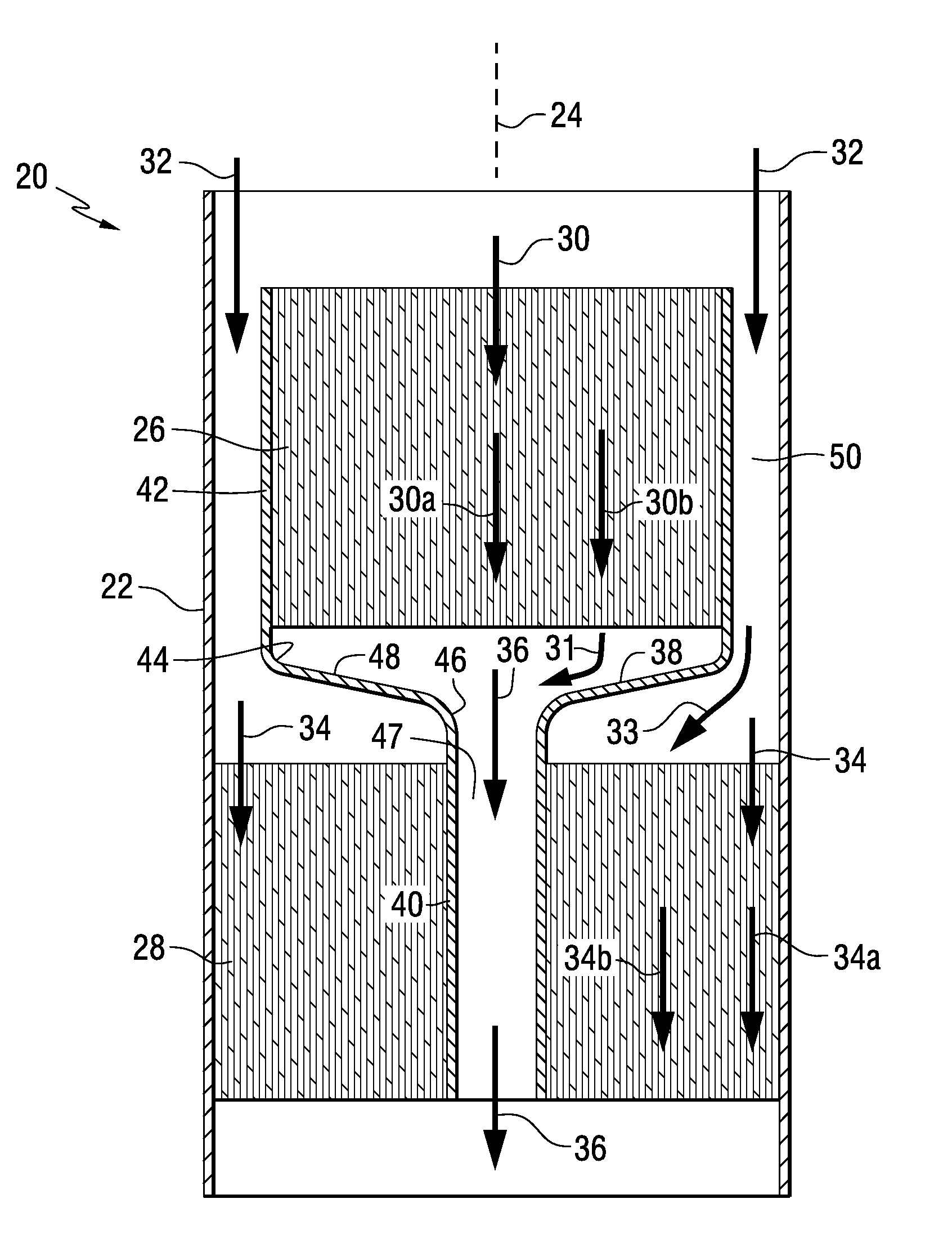
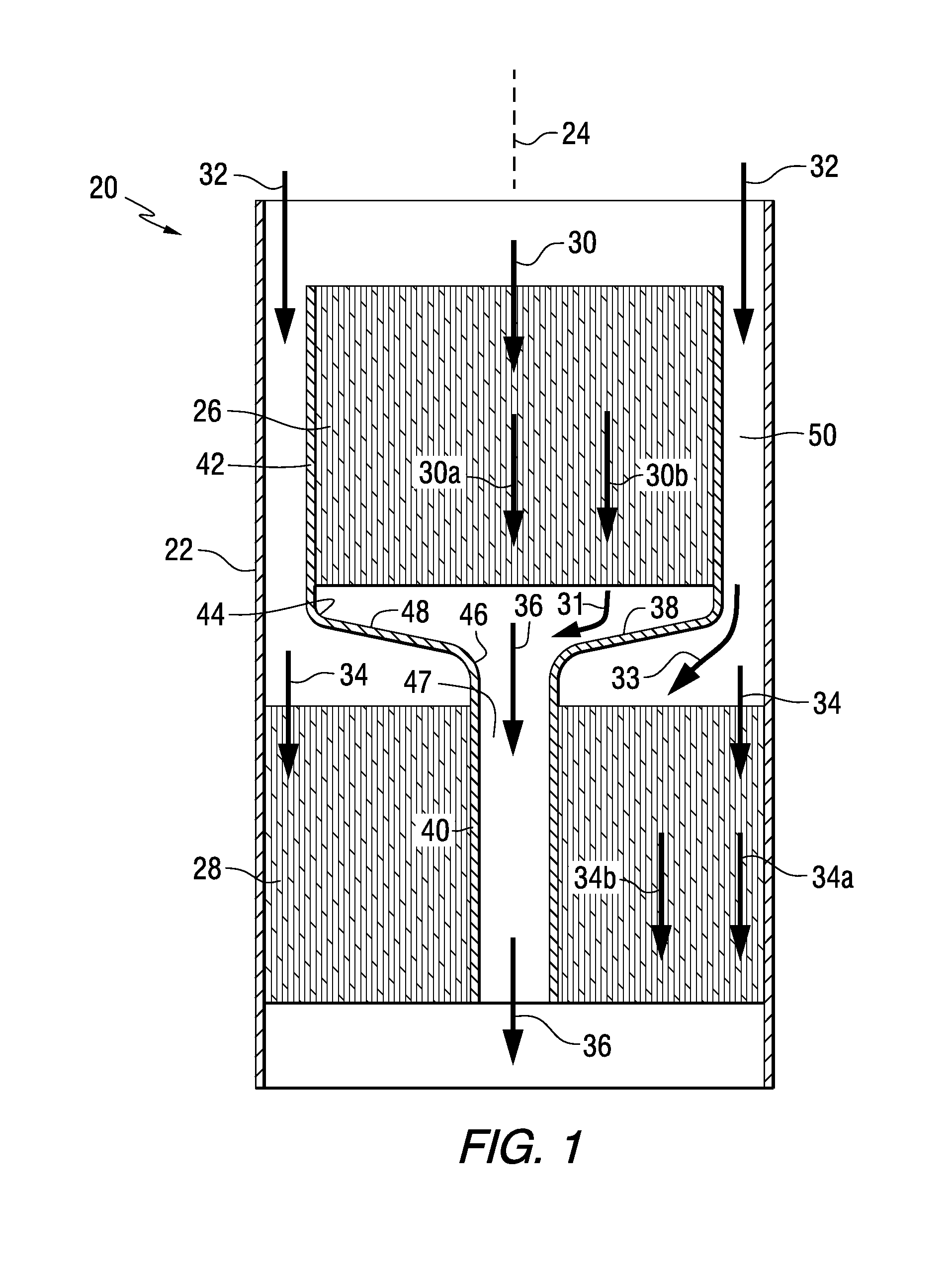
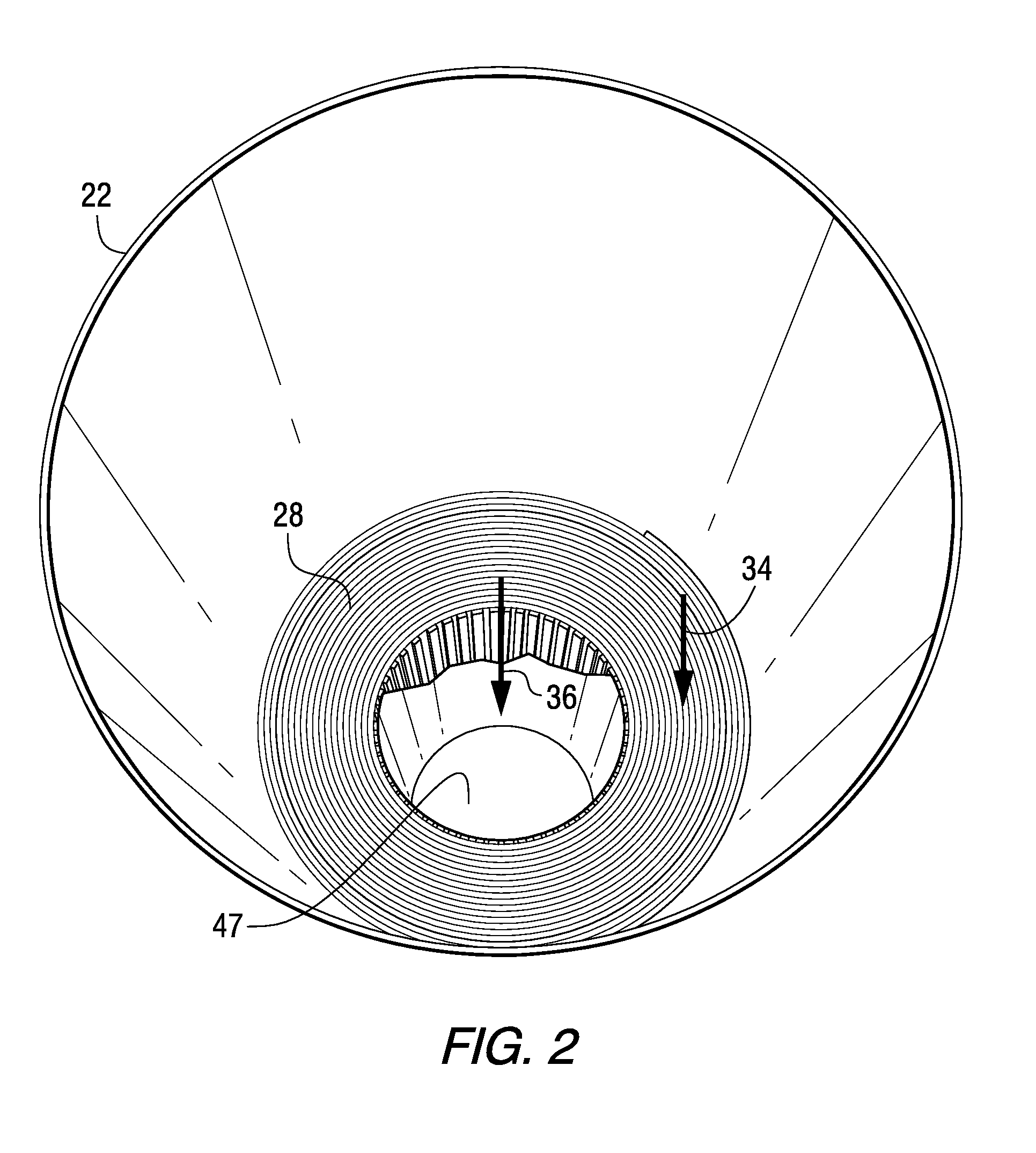
[0017]FIGS. 1-4 show a filter 20 for a housing 22 extending axially along an axial direction 24 and directing fluid along an axial flow path therethrough from upstream to downstream, e.g. downwardly in FIG. 1. The filter includes a plurality of annular filter elements such as 26, 28 for positioning in the housing. The annular filter elements may have an open center, as shown for annular filter element 28, or may have a closed center, with filter media extending all the way thereacross, as shown at annular filter element 26. The axis of the annulus of each annular filter element extends axially along axial direction 24. The annular filter elements are arranged in axially staggered relation in housing 22. The plurality of annular filter elements i...


PUM

PropertyMeasurementUnit
flow redirecting angleaaaaaaaaaa
diameteraaaaaaaaaa
liquidaaaaaaaaaa

Abstract

A filter includes a plurality of annular filter elements arranged in axially staggered relation. An axial flow path includes a plurality of flow path segments, some being filtered by a respective filter element, and others bypassing a respective filter element. Various combinations are provided.

Description

CROSS-REFERENCE TO RELATED APPLICATION[0001]This application claims the benefit of and priority from Provisional U.S. Patent Application No. 61 / 484,533, filed May 10, 2011, incorporated herein by reference.BACKGROUND AND SUMMARY[0002]The invention relates to filters for filtering fluid, including air, liquid, and other fluids.[0003]Filter arrangements with high packaging effectiveness and flexibility in layout remain a continuing need and challenge, including maintaining performance while maximizing space utilization.[0004]The present invention arose during continuing development efforts in the above technology.BRIEF DESCRIPTION OF THE DRAWINGS[0005]FIG. 1 is a schematic sectional view of a filter in accordance with the present disclosure.[0006]FIG. 2 is a perspective view of a portion of the filter of FIG. 1.[0007]FIG. 3 is a separated perspective view of the components of FIG. 1.[0008]FIG. 4 is an assembled view of the components of FIG. 3.[0009]FIG. 5 is a top view of one embodim...

Claims


Application Information

Patent Timeline
Patent Type & Authority Applications(United States)
IPC IPC(8): B01D29/54B01D46/00B01D37/00
CPCB01D29/073B01D29/216B01D29/54B01D35/02B01D46/0012B01D2275/208B01D46/2411B01D46/528B01D2275/206B01D2275/207B01D46/0021B01D46/60
Inventor HOLM, CHRISTOPHER E.CONNOR, MICHAEL J.HERMAN, PETER K.SCHWARTZ, SCOTT W.
Owner CUMMINS FILTRATION IP INC
Why Eureka
Try Eureka