Cabin air extraction system, method for operating a cabin air extraction system and aircraft air-conditioning system

a cabin air extraction and extraction system technology, applied in the direction of air-treatment apparatus arrangement, transportation and packaging, energy-saving board measures, etc., can solve the problems of further aerodynamic losses, energy-intensive methods, etc., and achieve efficient and fuel-saving operation, rapid regeneration of the desorption section, and optimal regeneration of the latter

Inactive Publication Date: 2016-07-28
AIRBUS OPERATIONS GMBH
View PDF10 Cites 6 Cited by
  • Summary
  • Abstract
  • Description
  • Claims
  • Application Information

AI Technical Summary

Benefits of technology

[0015]Moreover, the cabin waste air line may be connected via a bypass line, upstream of the filtering apparatus, to an air discharge aperture constructed in the outer skin of the aircraft. In particular, the bypass line may open into a nozzle which is adapted to produce a negative pressure in the area of the air discharge aperture constructed in the outer skin of the aircraft. A valve arranged in the bypass line may serve to control the flow of cabin waste air through the bypass line. An arrangement of this kind makes it possible to conduct the air discharged from the aircraft cabin directly away into the environment around the aircraft if necessary, for example in the event of failure of the filtering apparatus.
[0016]The cabin air extraction system may also comprise a heating apparatus which may be adapted to feed regeneration energy in the form of thermal energy to the desorption section of the rotary absorber. The heating apparatus may be constructed, for example, in the form of an electric heating apparatus or in the form of a heat source which is present in any case on board an aircraft equipped with the cabin air extraction system, and the heating apparatus guarantees rapid regeneration of the desorption section of the rotary absorber. In one preferred embodiment of the cabin air extraction system, the heating apparatus is adapted to warm up cabin waste air or filt

Problems solved by technology

Moreover, the reuse of cabin waste air permits a reduction in the air which is to be fed to the consumer device from

Method used


Image

  • Cabin air extraction system, method for operating a cabin air extraction system and aircraft air-conditioning system
  • Cabin air extraction system, method for operating a cabin air extraction system and aircraft air-conditioning system
  • Cabin air extraction system, method for operating a cabin air extraction system and aircraft air-conditioning system

Examples


Embodiment Construction

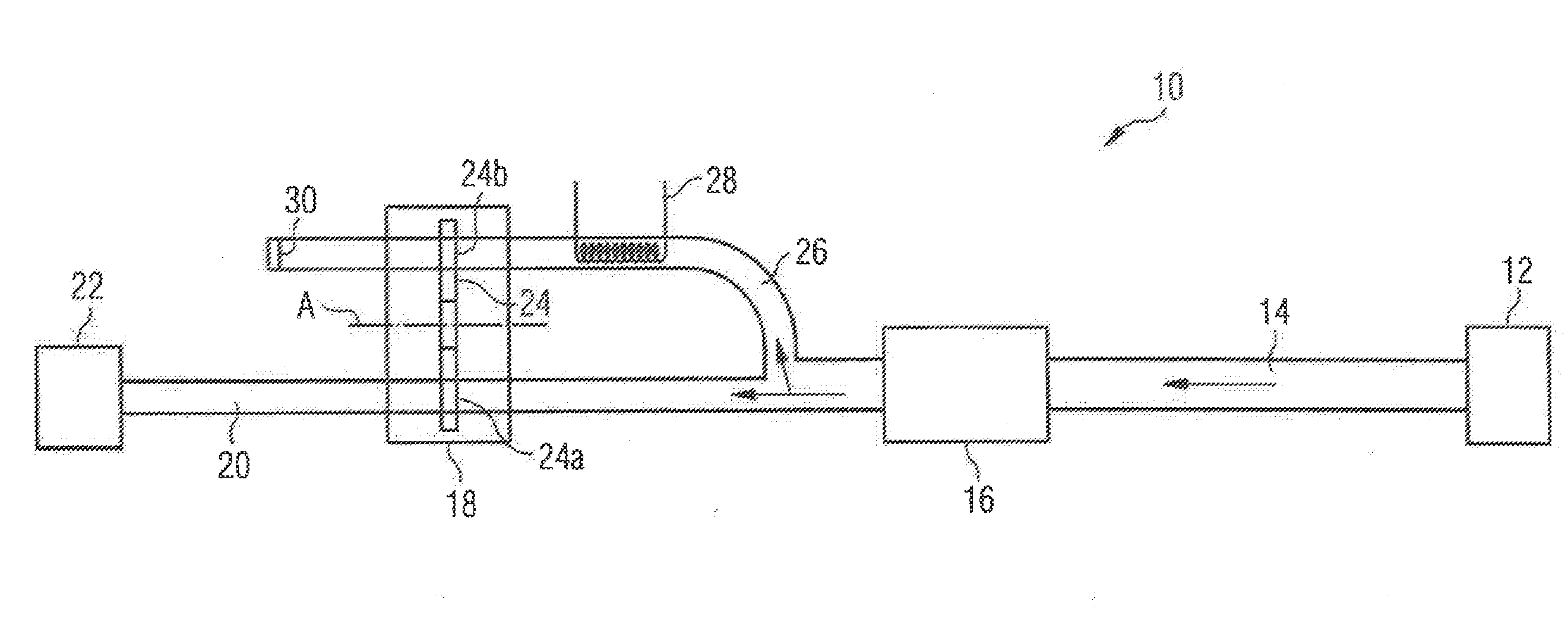
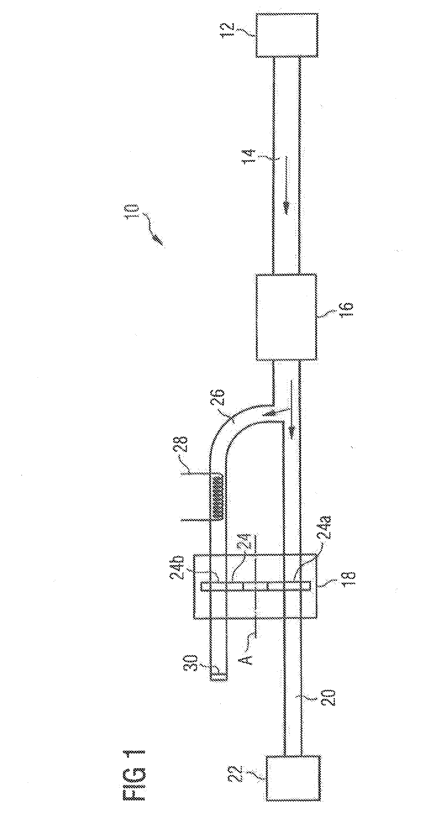
[0030]FIG. 1 shows a cabin air extraction system 10 which serves to discharge waste air and, in particular, unpleasant odors from an aircraft cabin 12. The cabin air extraction system 10 comprises a cabin waste air line 14, the first end of which is connected to the aircraft cabin 12, for example to a galley area of the aircraft cabin 12. A conveying apparatus 16, which in this case is constructed in the form of a blower, serves to convey, through the cabin waste air line 14, the cabin waste air which is to be discharged from the aircraft cabin 12. Arranged in the cabin waste air line 14 is a filtering apparatus 18 which is adapted to filter at least part of the cabin waste air flowing through the cabin waste air line 14.

[0031]In the arrangement shown in FIG. 1, the filtering apparatus 18 is arranged downstream of the conveying apparatus 16 in the cabin waste air line 14, that is to say, the conveying apparatus 16 is positioned upstream of the filtering apparatus 18 in the cabin was...


PUM


Abstract

A cabin air extraction system comprising a cabin waste air line and a conveying apparatus which conveys, through the cabin waste air line, waste air to be discharged from an aircraft cabin. A filtering apparatus filters at least part of the cabin waste air flowing through the cabin waste air line. Finally, the cabin air extraction system comprises a filtered air line which conducts at least part of the air which has been filtered by the filtering apparatus to a consumer device present on board an aircraft equipped with the cabin air extraction system.

Description

CROSS-REFERENCES TO RELATED APPLICATIONS[0001]This application claims the benefit of the German patent application No. 10 2015 201 342.1 filed on Jan. 27, 2015, the entire disclosures of which are incorporated herein by way of reference.BACKGROUND OF THE INVENTION[0002]The invention relates to a cabin air extraction system, a method for operating a cabin air extraction system and also an aircraft air-conditioning system.[0003]Modern commercial aircraft are usually equipped with a cabin air extraction system which serves to conduct waste air and unpleasant odors out of the aircraft cabin and into the environment around the aircraft. The cabin air extraction system comprises a cabin waste air line in which there is arranged a conveying apparatus which is constructed, for example, in the form of a blower. By means of this conveying apparatus, cabin waste air is conveyed out of the cabin through the cabin waste air line and finally discharged to the environment around the aircraft via a...

Claims


Application Information

Patent Timeline
IPC IPC(8): B64D13/06B64D13/08
CPCB64D13/06B64D2013/003B64D2013/0651B64D13/08B64D2013/0688Y02T50/50
Inventor HOLTRUP, BERNHARDKUHNKE, PHILIP
Owner AIRBUS OPERATIONS GMBH
Why Eureka
Try Eureka