
Pressure Discharge Valve For Storage Tanks

a technology for pressure discharge valves and storage tanks, applied in mechanical equipment, functional valve types, transportation and packaging, etc., can solve problems such as high order detonation, and achieve the effect of decreasing frictional resistan

Active Publication Date: 2012-11-15
KOTEFSKI STOJAN +1
View PDF2 Cites 6 Cited by
  • Summary
  • Abstract
  • Description
  • Claims
  • Application Information

AI Technical Summary

Benefits of technology

[0017]In a second preferred embodiment, there is provided in connection with the first preferred embodiment a pressure discharge valve in which a temperature differential between venting of the first vent means and the second vent means can be adjusted to provide a specific time / temperature interval to provide safer conditions for firefighters.
[0052]In a twenty first preferred embodiment, there is provided in connection with the first, fifteenth and twentieth preferred embodiments, a pressure discharge valve further comprising a eutectic sodder material disposed between the plug and valve body / valve body means, said eutectic sodder material being solid at normal operating temperatures but operable to change phase to a liquid at or near critical conditions, thereby acting as a lubricant in decreasing frictional resistance between the plug and valve body.

Problems solved by technology

In particular, a pressure discharge valve for storage tanks containing flammable and / or explosive liquids was unexpectedly discovered which automatically opens and vents said liquids before the temperature and / or pressure in the tank causes the tank to rupture, and which may otherwise cause a high order detonation.

Method used


Image

  • Pressure Discharge Valve For Storage Tanks
  • Pressure Discharge Valve For Storage Tanks
  • Pressure Discharge Valve For Storage Tanks

Examples


Embodiment Construction

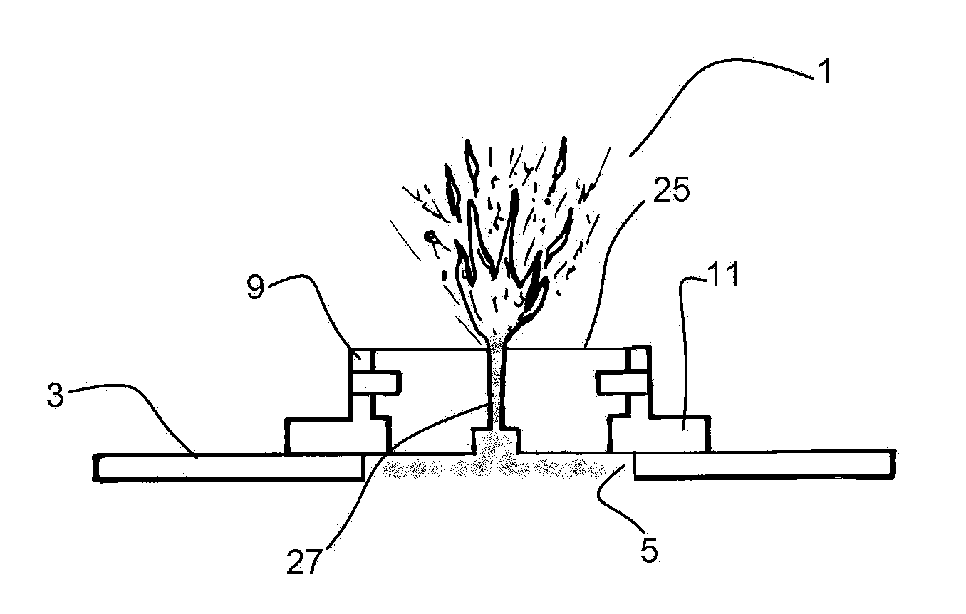
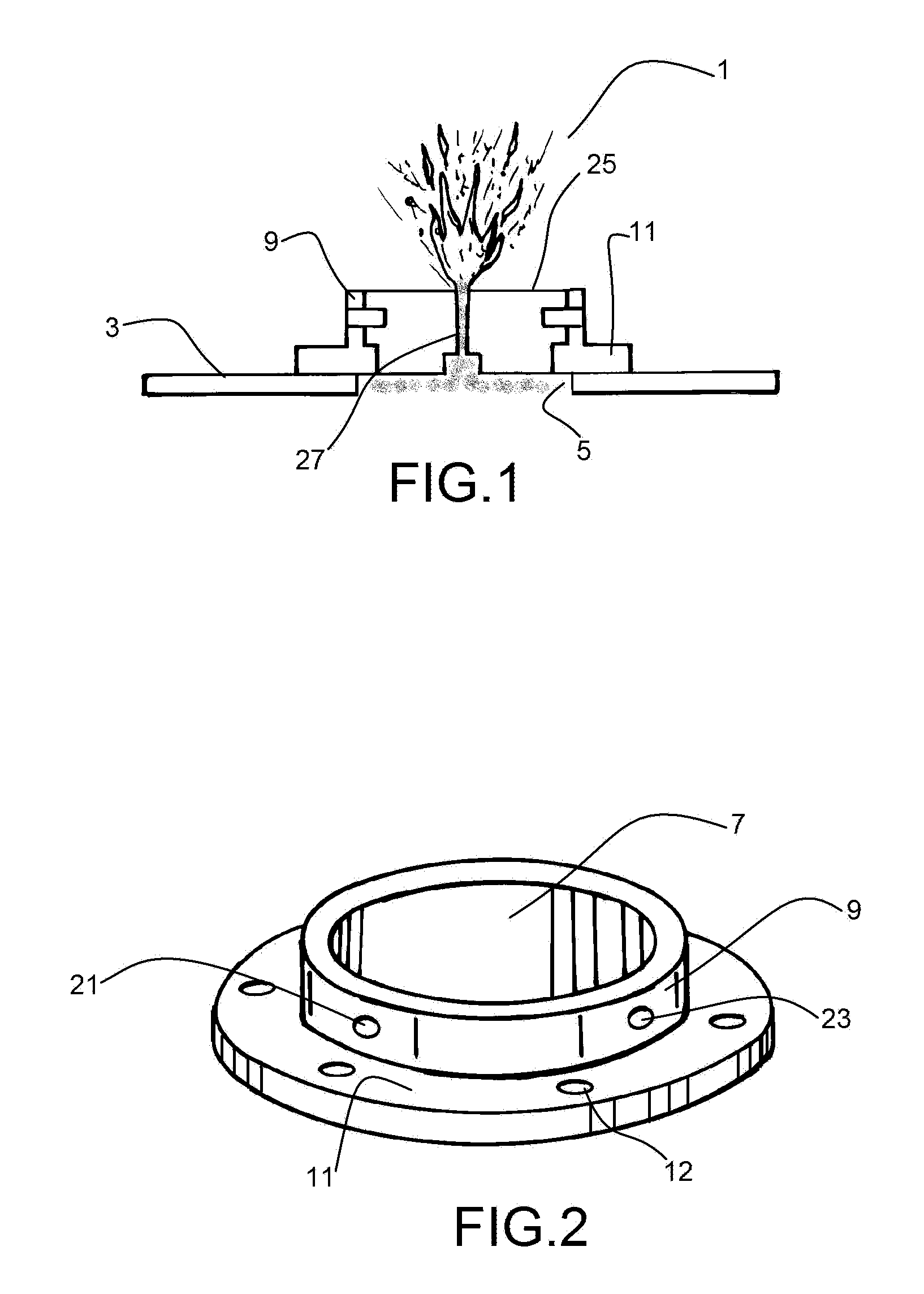
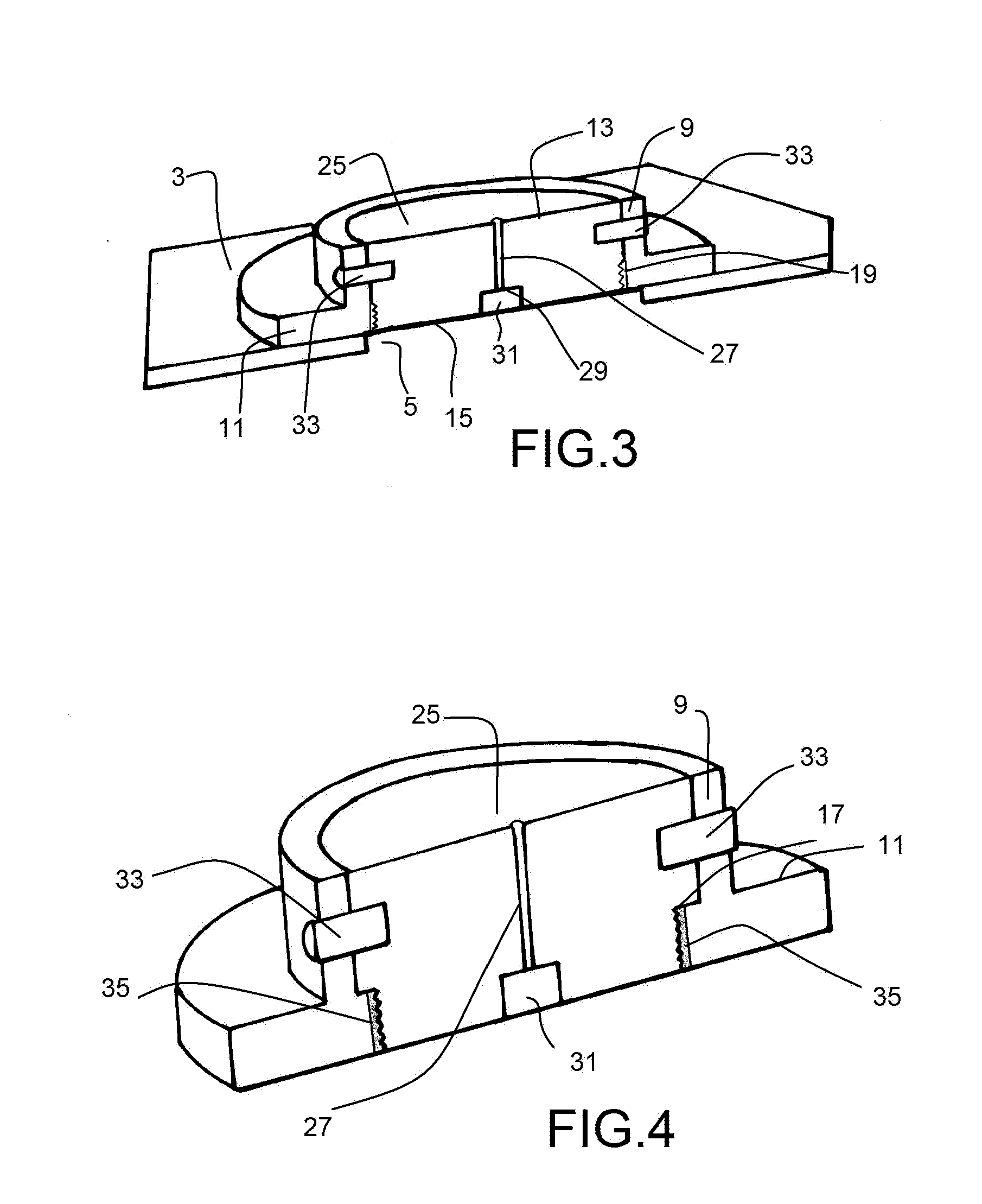
[0064]The pressure discharge valve of the present invention is shown generally at 1 in FIG. 1, mounted on wall 3 of a storage tank for flammable or explosive fuels (not shown). A hole 5 in storage tank wall 3 communicates with a bore hole 7 (FIGS. 2 and 5) formed in body 9 of valve 1 (FIGS. 1, 2, 6, and 7). A flange 11 is shown connected to or formed integral with valve body 9 (FIGS. 1-7), the purpose of flange 11 being to facilitate the mounting of valve 1 on wall 3 of a storage tank. Holes 12 through flange 11 can be used in mounting valve 1 (FIGS. 2-4).

[0065]The bore hole 7 through valve body 9 has a larger diameter 13 at an outer or discharge end than at a lower or entry end 15 which is in contact with the fuel tank (see FIGS. 3-7). As shown in FIGS. 3-7, a shoulder 17 is formed on an inner surface of bore hole 7 where the bore hole changes diameter. Threads 19 are formed on an inner surface of the smaller diameter bore hole 15 in valve body 9 (FIGS. 3-7). Small bore holes 21, 2...


PUM


Abstract

A pressure discharge valve for storage tanks on land or trucks including a valve body having a through hole therein adapted to mate and communicate with a through hole in a wall of the storage tank, a first vent means comprised of a eutectic composition which automatically provides a partial release of storage tank liquid at a first predetermined temperature lower than critical combustion and / or explosive temperatures of liquid in the storage tank, to provide a visual signal and warning to firefighters of these hazardous conditions, and a second vent means comprised of a eutectic composition to automatically vent liquid in the storage tank through the hole in the valve body when the liquids therein reach a predetermined critical temperature. In addition, the pressure discharge valve preferably comprises a eutectic solder material disposed between the valve body and the second vent means, which changes phase (i.e., reaches its eutectic point) below the eutectic point of the second vent means, thereby providing a lubricant between the plug and the valve body.

Description

BACKGROUND OF THE INVENTION[0001]1. Field of the Invention[0002]The present invention relates in general to a pressure discharge valve for storage tanks containing petroleum products, acid, liquefied gases, and other flammable liquids and, more particularly, to a pressure discharge valve comprised of a eutectic composition designed to automatically vent when the contents of the storage tank reaches a predetermined dangerous temperature lower than a critical vent temperature.[0003]2. Description of the Related Art[0004]In general, storage tanks such as fuel tanks have operating temperatures between −60° F. to 160° F. In case of a fire, the temperature of the storage tank(s) rises beyond a safe operating temperature of, for example, 160° F., and the liquid contained inside the tank expands and creates an internal pressure (Hoop Pressure). At a certain point, as the internal pressure increases, the tank ruptures and creates a high order explosion.[0005]If this hoop pressure were to be ...

Claims


Application Information

Patent Timeline
IPC IPC(8): B65D90/32
CPCB65D90/32F16K17/383F16K17/003F42B39/14B65D90/36F42B27/00Y10T137/1797Y10T137/1812
Inventor KOTEFSKI, STOJANREDA, EUGENE R.
Owner KOTEFSKI STOJAN
Learn More