Device for attaching an aircraft engine, comprising blocks for clamping an engine attachment with a wedge effect

a technology for aircraft engines and wedge effects, applied in the direction of machine supports, manufacturing tools, transportation and packaging, etc., can solve the problems of difficult application by a single operator, traction bolts, and insufficient friction between connecting plates, so as to achieve simple economical and efficient solutions

Active Publication Date: 2012-11-15
AIRBUS OPERATIONS (SAS)
View PDF10 Cites 8 Cited by
  • Summary
  • Abstract
  • Description
  • Claims
  • Application Information

AI Technical Summary

Benefits of technology

[0013]The object of the invention is notably to provide a simple economical and efficient solution to these problems, with which at least part of the aforementioned drawbacks may be avoided.

Problems solved by technology

However, this type of configuration requires the use of relatively bulky and massive traction bolts 22, and requires that a tightening torque of high level be applied to these bolts, which is difficult to apply by a single operator, so that the tightening of these bolts is usually applied jointly by two operators.
Moreover, the traction bolts 22 do not allow sufficient friction between the connecting plates 12, 16 in order to prevent relative sliding of the plates due to the play of the mounting of the aforementioned centering pins.

Method used


Image

  • Device for attaching an aircraft engine, comprising blocks for clamping an engine attachment with a wedge effect
  • Device for attaching an aircraft engine, comprising blocks for clamping an engine attachment with a wedge effect
  • Device for attaching an aircraft engine, comprising blocks for clamping an engine attachment with a wedge effect

Examples


Embodiment Construction

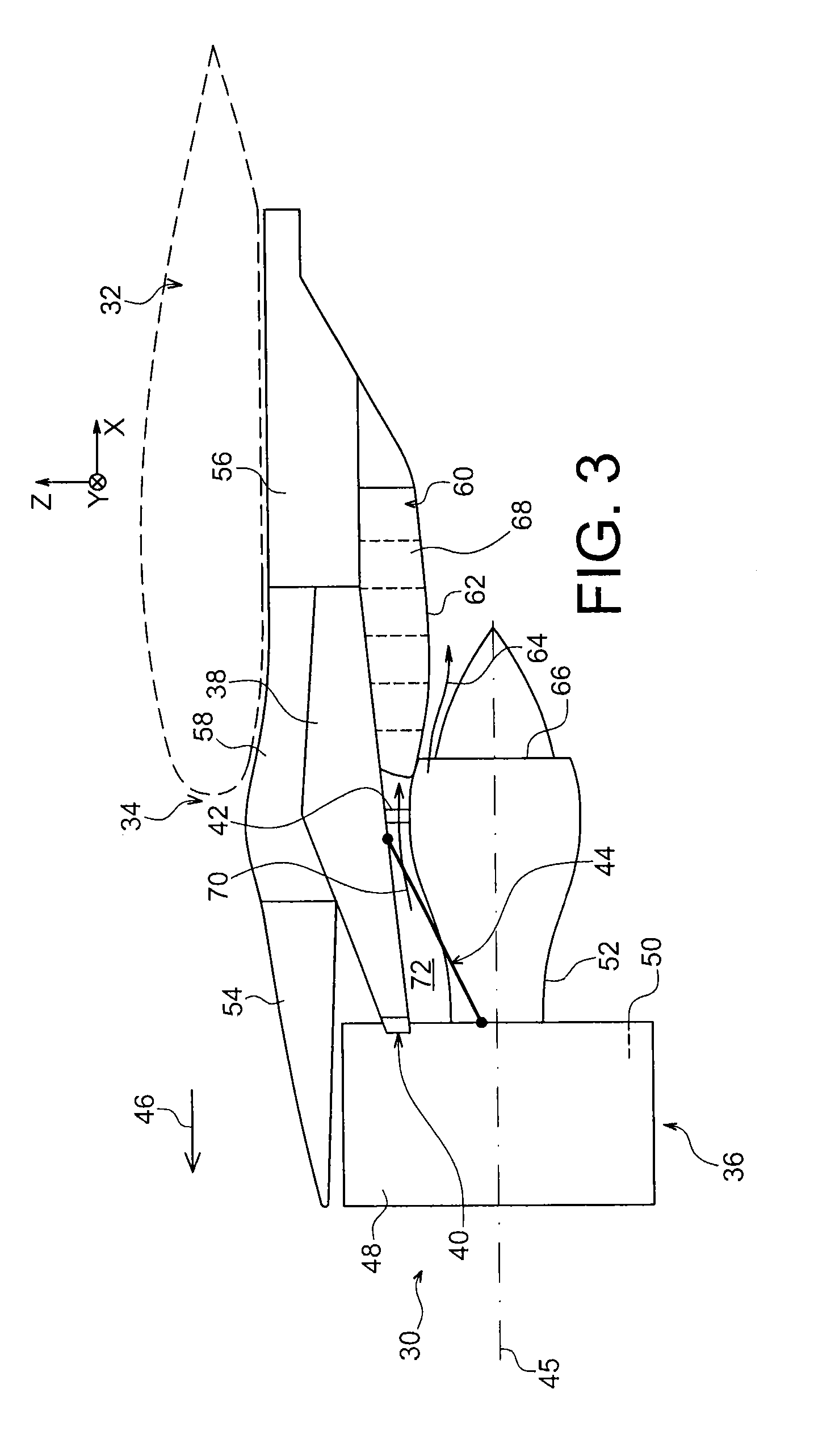
[0054]With reference to FIG. 3, an engine assembly 30 for an aircraft is seen, intended to be attached under a wing 32 of this aircraft, this assembly 30 including a mounting device or pylon 34 according to a first preferred embodiment of the present invention, as well as an engine 36, such as a jet turbine engine, attached under this mounting pylon 34.

[0055]Globally, the mounting pylon 34 includes a rigid structure 38, also called a primary structure, and means for attaching the engine 36 to this structure 38, these attachment means comprising engine attachments 40, 42 as well as a device 44 for taking up the thrust forces generated by the engine 36.

[0056]As an indication, it is noted that the engine assembly 30 is intended to be surrounded by a nacelle (not shown), and the mounting pylon 34 includes another series of attachments (not shown) added onto the rigid structure 38 and enabling the hanging of this assembly 30 under the wing 32 of the aircraft.

[0057]In the whole descriptio...


PUM

PropertyMeasurementUnit
angleaaaaaaaaaa
forceaaaaaaaaaa
shapeaaaaaaaaaa

Abstract

A device for mounting an aircraft engine, including a rigid structure, an engine attachment including a connecting plate superposed to an associated connecting plate of said rigid structure, and means for mutually tightening said plates comprising at least one wedge-effect tightening block and corresponding bearing surfaces of said plates which are conformed so that, when each tightening block is applied against said bearing surfaces along a direction parallel to the plane of the contact surface between both of these plates, this block exerts by a wedge-effect a force for tightening these plates against each other along a direction perpendicular to said plane.

Description

TECHNICAL FIELD[0001]The present invention generally relates to a device for mounting an aircraft engine, for example intended to be interposed between an aircraft wing and the relevant engine, as well as to an engine unit comprising such a mounting device.[0002]The invention also relates to a method for fixing an engine attachment to a rigid structure of such an attachment device. It may be used on any type of aircraft equipped with jet turbine engines or turboprops.[0003]This type of mounting device, also called a mounting pylon or “EMS” (“Engine Mounting Structure”), may equally be used for hanging an engine below the wing of the aircraft, for mounting this engine above this same wing, or else further for fixing this engine to the rear portion of the fuselage of the aircraft.STATE OF THE PRIOR ART[0004]Actually, such a mounting device is usually provided for forming the connection interface between a turbine engine and a wing of the aircraft. It allows transmission to the structu...

Claims


Application Information

Patent Timeline
Patent Type & Authority Applications(United States)
IPC IPC(8): F16M13/02B23P11/00
CPCB64D2027/266Y10T29/49826B64D27/26B64D2027/264
Inventor MARCHE, HERVE
Owner AIRBUS OPERATIONS (SAS)
Why Eureka
Try Eureka