Intake enhancement system for a vehicle

a technology of inlet enhancement and vehicle, which is applied in the direction of combustion engine/fuel air treatment, machines/engines, mechanical equipment, etc., can solve the problems of preventing the airflow from being heated up, affecting the efficiency of the internal combustion engine at warmer ambient temperatures, and damage to the engine, so as to reduce the installation cost, minimize the manufacturing cost, and enhance the heat exchange

Inactive Publication Date: 2012-12-27
BURKE FREDERICO
View PDF12 Cites 8 Cited by
  • Summary
  • Abstract
  • Description
  • Claims
  • Application Information

AI Technical Summary

Benefits of technology

[0008]Another advantage of the invention is to provide an intake enhancement system, wherein the combustion element, i.e. the airflow and / or a flow of fuel, is cooled down by the existing air conditioning or the intercooler of the vehicle while being energy efficient.
[0009]Another advantage of the invention is to provide an intake enhancement system, wherein the combustion element is guided to flow along the heat exchanging duct of the heat exchanger of the vehicle in a spiral direction for enhancing the heat-exchange between the combustion element and the heat exchanging agent.
[0010]Another advantage of the invention is to provide an intake enhancement system, which does not require altering the original structural design of the heat exchanger of the vehicle to incorporate with the intake enhancement system, so as to minimize the installation cost of the present invention to be used in the vehicle.
[0011]Another advantage of the invention is to provide an intake enhancement system, which does not involve complicated or expensive mechanical components to minimize the manufacturing cost of the present invention.
[0012]Another advantage of the invention is to provide an intake enhancement system, wherein no expensive or complicated mechanical structure is required to be employed in the present invention in order to achieve the above mentioned objects. Therefore, the present invention successfully provides an economical and efficient solution for providing an intake enhancement system to incorporate in any existing vehicle having a heat exchanger in order to cool down the combustion element before the combustion element enters into the internal combustion engine.
[0013]Additional advantages and features of the invention will become apparent from the description which follows, and may be realized by means of the instrumentalities and combinations particular point out in the appended claims.

Problems solved by technology

It is a scientific fact that an internal combustion engine operates less efficiently at warmer ambient temperatures.
Accordingly, warmer air intake combined with warm fuel creates a potentially lean condition or “vapor lock” that can damage the engine.
However, the heat shield can only prevent the airflow being heated up by the heat generated from the engine; it does not cool down the airflow before the airflow enters into the engine.

Method used


Image

  • Intake enhancement system for a vehicle
  • Intake enhancement system for a vehicle
  • Intake enhancement system for a vehicle

Examples


Embodiment Construction

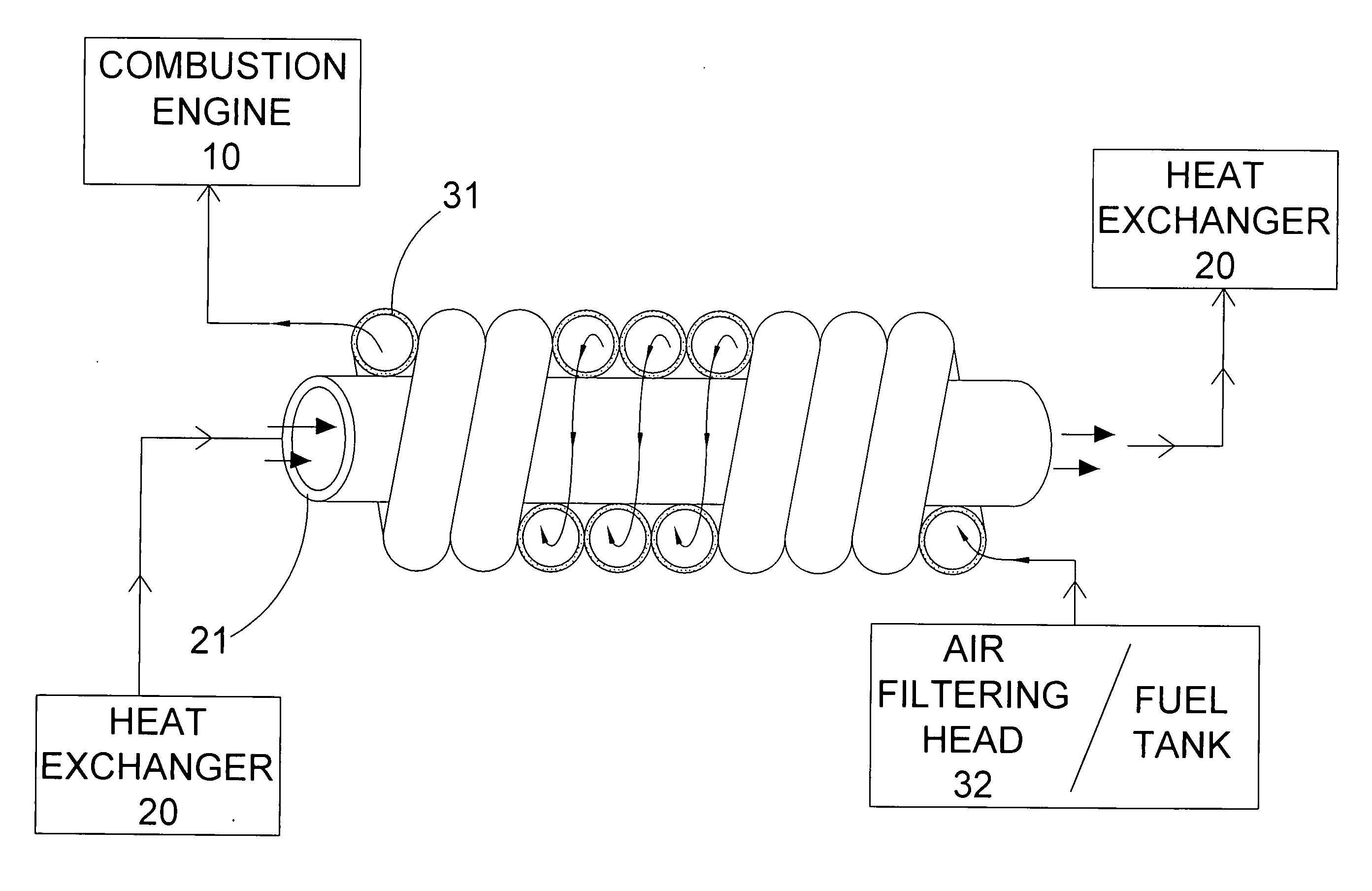
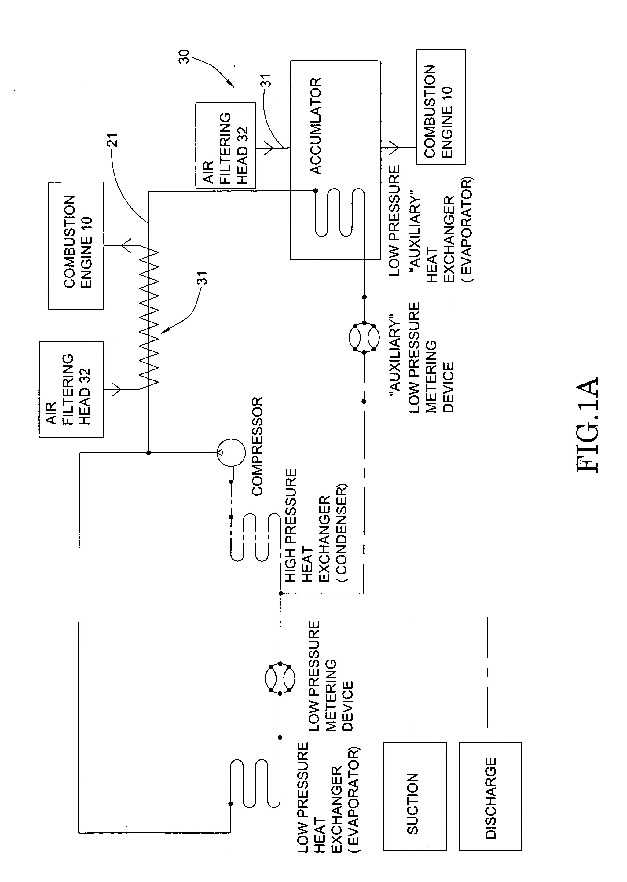
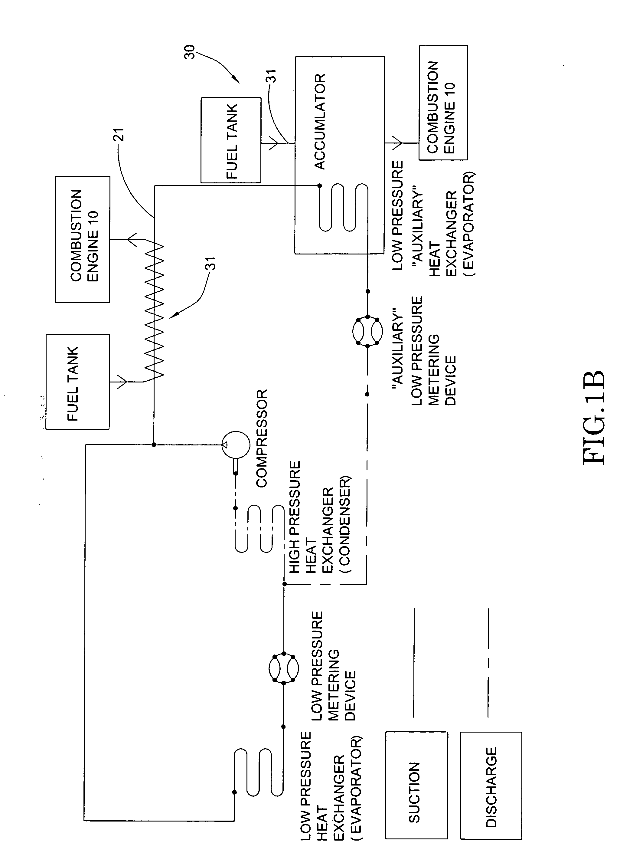
[0030]Referring to FIGS. 1A and 1B of the drawings, an intake enhancement system for a vehicle according to a preferred embodiment of the present invention is illustrated. Accordingly, the vehicle, such as a car, motorcycle, boat, or truck, generally comprises an internal combustion engine 10 and a heat exchanger 20 for generating a cooling effect.

[0031]The heat exchanger 20, which can be an air conditioning system, comprises a compressor, a condenser, an evaporator, and a heat exchanging line operatively connecting the compressor, condenser, and evaporator for guiding a flow of heat exchanging agent, such as refrigerant, among the compressor, condenser, and evaporator for heat exchange. In particular, a heat exchanging duct 21 is formed along the heat exchanging line to operatively link all components of the heat exchanger 20.

[0032]The heat exchanger 20 further defines a low pressure side and a high pressure side. The low pressure side of the heat exchanger 20 is defined at the por...


PUM


Abstract

An intake enhancement system is arranged for incorporating with a vehicle which includes a combustion engine and a heat exchanger for generating a cooling effect. The intake enhancement system includes an intake cooling unit for delivering a combustion element to the combustion engine, wherein the intake cooling unit is thermally conducted with the heat exchanger for heat-exchanging the combustion element with heat exchanging agent of the heat exchanger so as to substantially cool down the combustion element along the intake cooling unit before the combustion element delivers to the combustion engine.

Description

BACKGROUND OF THE PRESENT INVENTION[0001]1. Field of Invention[0002]The present invention relates to a vehicle fuel system, and more particularly to an intake enhancement system, which substantially cools the air / fuel intake before the air / fuel enters into the internal combustion engine so as to maximize the efficiency of the internal combustion engine.[0003]2. Description of Related Arts[0004]It is a scientific fact that an internal combustion engine operates less efficiently at warmer ambient temperatures. Accordingly, warmer air intake combined with warm fuel creates a potentially lean condition or “vapor lock” that can damage the engine. A cold air intake can cool down the air flow before entering into the internal combustion engine in order to increase engine power and efficiency and to improve throttle response and fuel economy in most cases.[0005]A conventional cold air intake is an external device installed into the vehicle in order to incorporate with the air intake system ...

Claims


Application Information

Patent Timeline
Patent Type & Authority Applications(United States)
IPC IPC(8): F02M31/20
CPCF02B29/0443F02M31/20Y02T10/126Y02T10/146F01P3/20Y02T10/12
Inventor BURKE, FREDERICO
Owner BURKE FREDERICO
Why Eureka
Try Eureka