
LED lighting circuit

a technology of led lighting and circuits, which is applied in the direction of lighting apparatus, electroluminescent light sources, light sources, etc., can solve the problems of reducing the lifetime of the ac-led chip, affecting the operation of the lighting circuit, and exhibiting unacceptably high optical flicker

Inactive Publication Date: 2012-11-15
KONINKLIJKE PHILIPS ELECTRONICS NV
View PDF2 Cites 23 Cited by
  • Summary
  • Abstract
  • Description
  • Claims
  • Application Information

AI Technical Summary

Benefits of technology

The invention provides an improved way to drive an AC-LED chip with a DC input signal. The AC-LED lighting circuit uses a polarity-selectable DC signal, which can be a fixed-polarity DC input signal or a converted DC signal. The circuit can be used with either an AC or DC power supply. The circuit can be designed as a retro-fit device for existing lighting fixtures, and can be easily incorporated into a lighting device. The circuit allows for the selection of the polarity of the DC signal to drive either the first or second set of LEDs, providing flexibility in the choice of which string of LEDs to drive. The AC-LED lighting device can be designed as a low-energy replacement for traditional light bulbs. The invention provides an improved way to control the polarity of the DC signal to drive the AC-LED chip, allowing for better flicker-free light output.

Problems solved by technology

However, the light produced by AC-LEDs driven from the AC mains supply can exhibit an unacceptably high degree of optical flicker, caused by the rapid alteration in polarity at mains frequency.
This flicker can be irritating, particularly in the case of indoor lighting applications.
However, in this mode of operation, only one part of the AC-LED chip is continually driven with a forward current, while the other part is continually exposed to a reverse bias voltage and is effectively not used.
Apart from the poor utilization, this mode of operation leads to a reduction in lifetime of the AC-LED chip, because, when driven continually with a DC signal, only one of the two strings of LEDs is continually ‘stressed’ with a drive signal to generate light.

Method used


Image

  • LED lighting circuit
  • LED lighting circuit
  • LED lighting circuit

Examples


Embodiment Construction

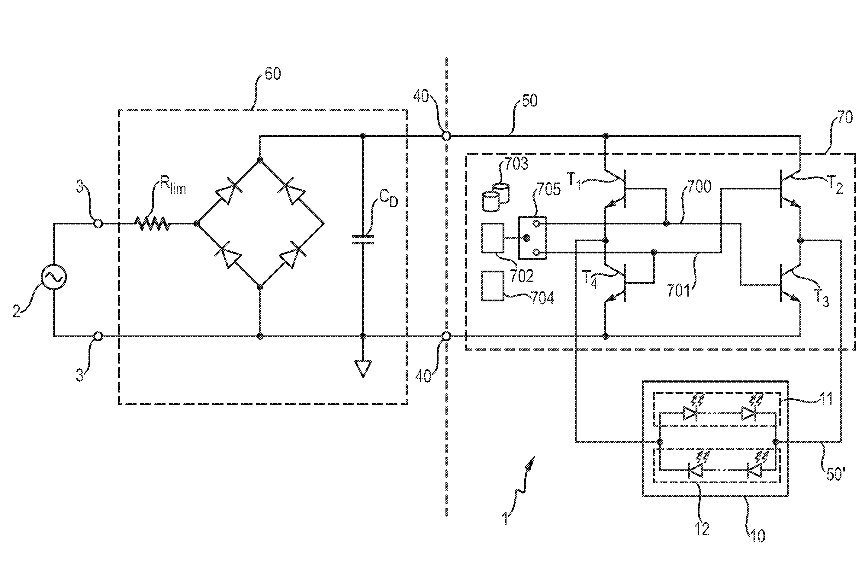
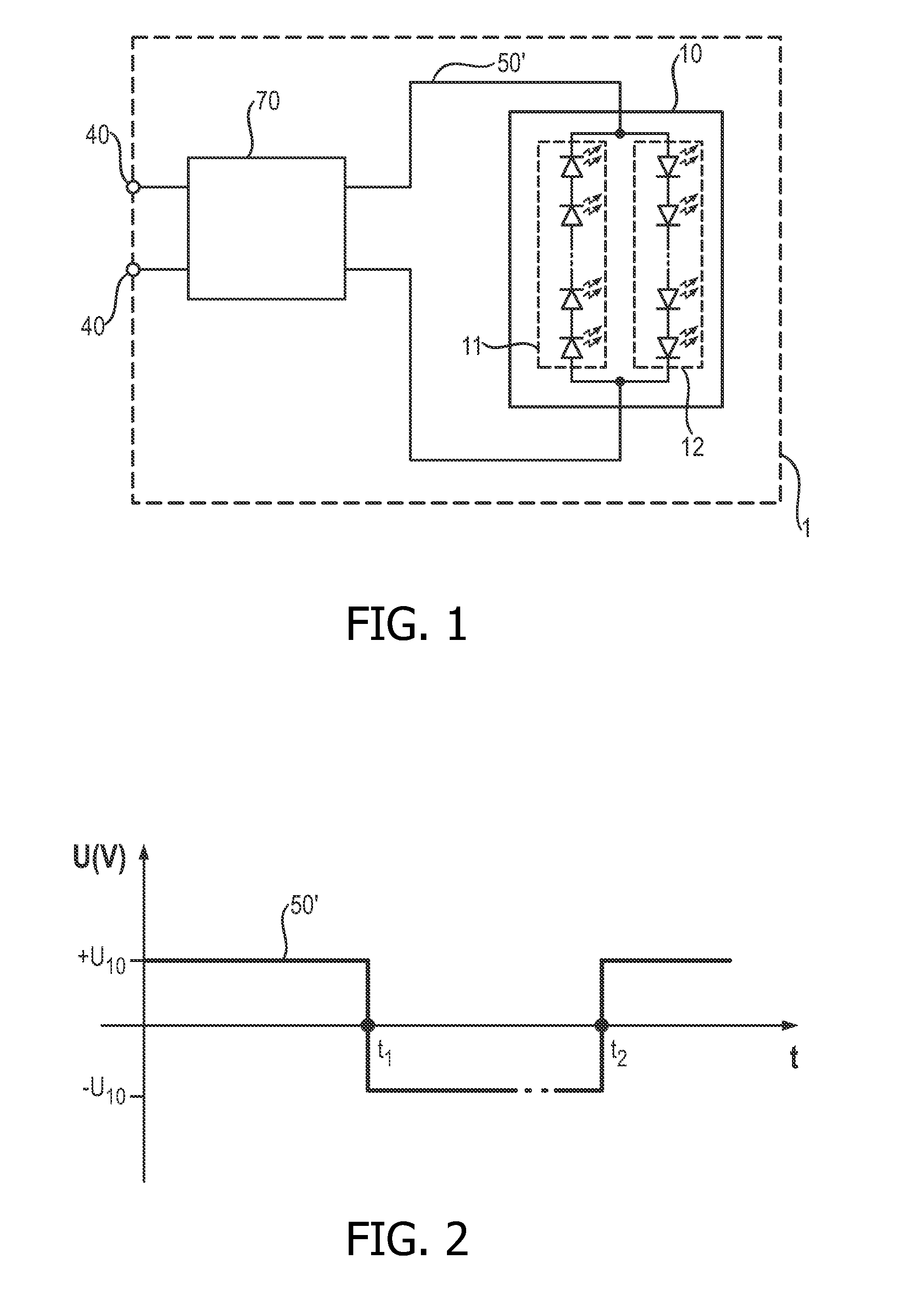
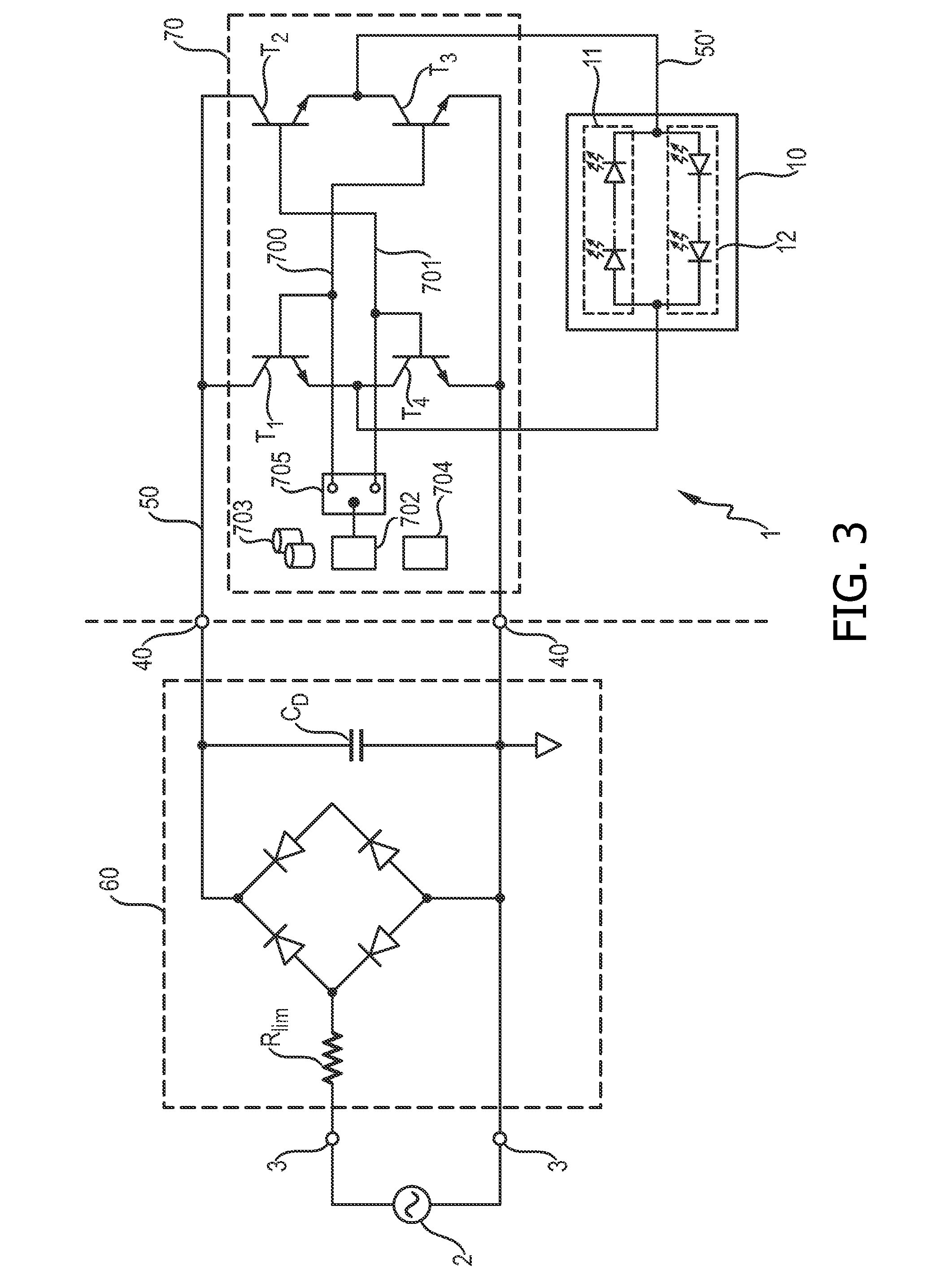
[0053]FIG. 1 shows a simplified circuit diagram in which an AC-LED lighting circuit 1 can be connected, by means of suitable connectors 40, to a DC power supply of constant or fixed polarity. A polarity controller 70 uses the fixed-polarity DC signal to derive or generate a polarity-selectable DC signal 50′ which toggles as required between positive and negative polarity and which is applied to an AC-LED arrangement 10. The AC-LED arrangement 10 essentially comprises two strings 11, 12 of LEDs (represented by the standard circuit symbol), connected inverse parallel so that, for an applied potential, one string conducts while the other string is reverse biased. Of course, as the skilled person will appreciate, the AC-LED arrangement 10 can comprise several chips connected in series or in parallel, depending on the desired light output, and any of these chips can comprise more than two strings.

[0054]FIG. 2 shows an idealized voltage 50′ applied to the AC-LED arrangement 10 of FIG. 1. ...


PUM


Abstract

The invention describes an AC-LED lighting circuit (1) comprising an AC-LED arrangement (10) with at least a first set (11) of LEDs connected according to a first polarity and a second set (12) of LEDs connected according to the opposite polarity, which AC-LED lighting circuit (1) is characterized by (i) a source (61) of a polarity-selectable DC input signal (51) to be applied to the AC-LED arrangement (10), or a connecting means (40) for connecting the AC-LED lighting circuit (1) to a fixed-polarity DC input signal (50) and a conversion means (T1, T2, T3, T4) for converting the fixed-polarity DC input signal (50) to a polarity-selectable DC signal (50′) to be applied to the AC-LED arrangement (10); and (ii) a polarity controller (70, 71) realized to control the polarity of the polarity-selectable DC signal (50′, 51) applied to the AC-LED arrangement (10) such that the first set (11) of LEDs of the AC-LED arrangement (10) is driven when the polarity-selectable DC signal (50′, 51) has the first polarity, and the second set (12) of LEDs of the AC-LED arrangement (10) is driven when the polarity-selectable DC signal (50′, 51) has the opposite polarity. The invention further describes an AC-LED lighting device (9) comprising such an AC-LED lighting circuit (1) and having an outer chamber (90) enclosing the AC-LED arrangement (10) of the AC-LED lighting circuit (1) and a lamp base at least partially incorporating the connector (3) of the AC-LED lighting circuit (1). The invention also describes a method of driving an AC-LED lighting circuit comprising an AC-LED arrangement (10).

Description

FIELD OF THE INVENTION[0001]The invention describes an LED lighting circuit, an AC-LED lighting device and a method of driving an LED lighting circuit.BACKGROUND OF THE INVENTION[0002]In lighting solutions, LEDs (light-emitting diodes) are playing an ever greater role, made possible by the advances in LED technology in recent years. LED lighting arrangements can be designed to emit white light, necessary for indoor and outdoor illumination purposes, by combining red, green and blue LEDs in solid-state lighting (SSL) solutions. Some LEDs can be coated with phosphor to convert the emitted light into another colour, for example blue ‘pump’ light can be converted into yellow, green or red light. Such coated LEDs can be combined with non-coated LEDs in an arrangement to give white light. Typically, phosphor-converted white-emitting LEDs are obtained by a combination of phosphor-converted yellowish light and some part of the blue pump light. The development of LEDs with a high light outpu...

Claims


Application Information

Patent Timeline
Patent Type & Authority Applications(United States)
IPC IPC(8): H05B37/00H05B44/00
CPCH05B33/0815H05B33/0803H05B45/37
Inventor RADERMACHER, HARALD JOSEF GUNTHER
Owner KONINKLIJKE PHILIPS ELECTRONICS NV
Learn More