
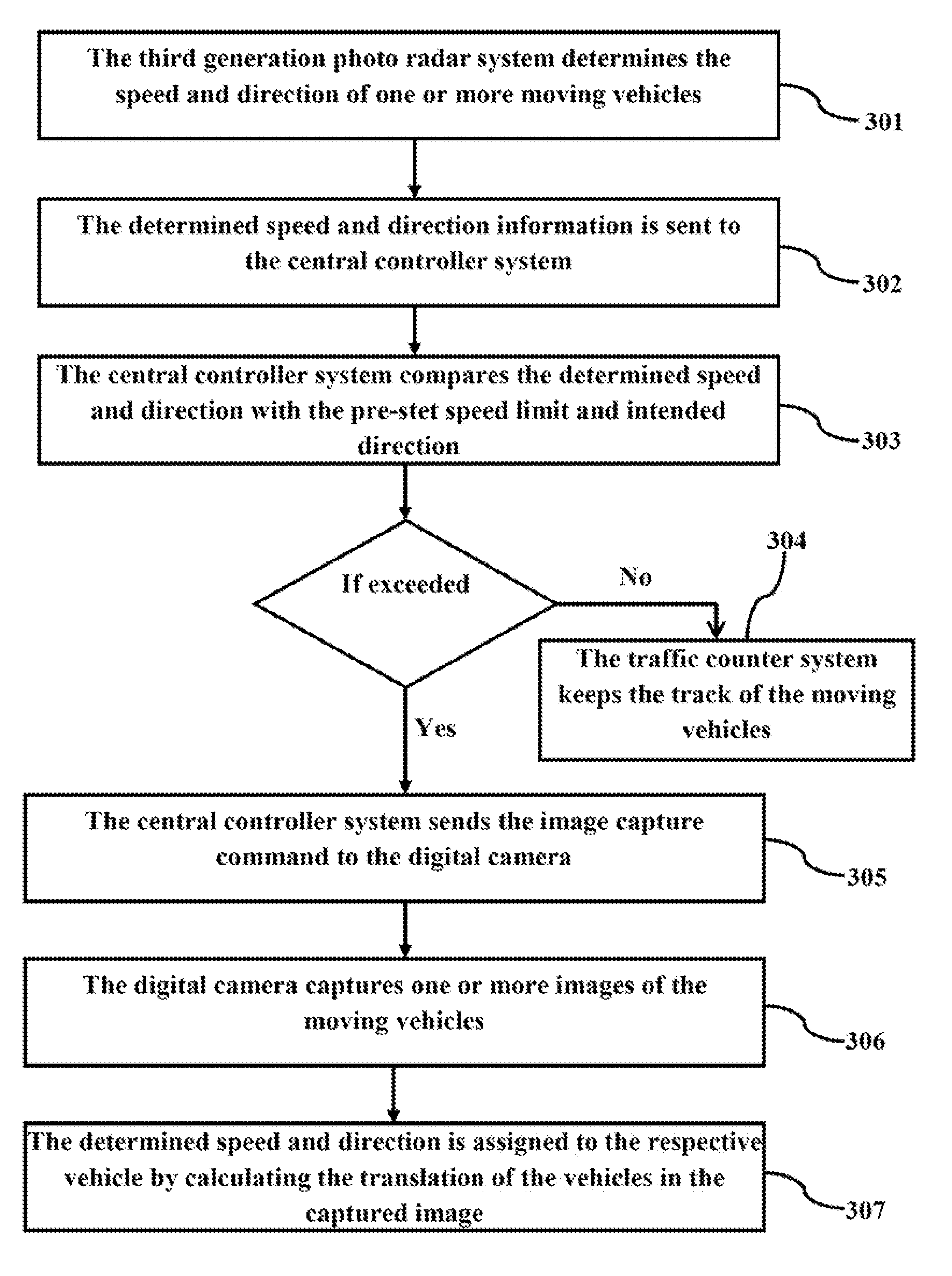
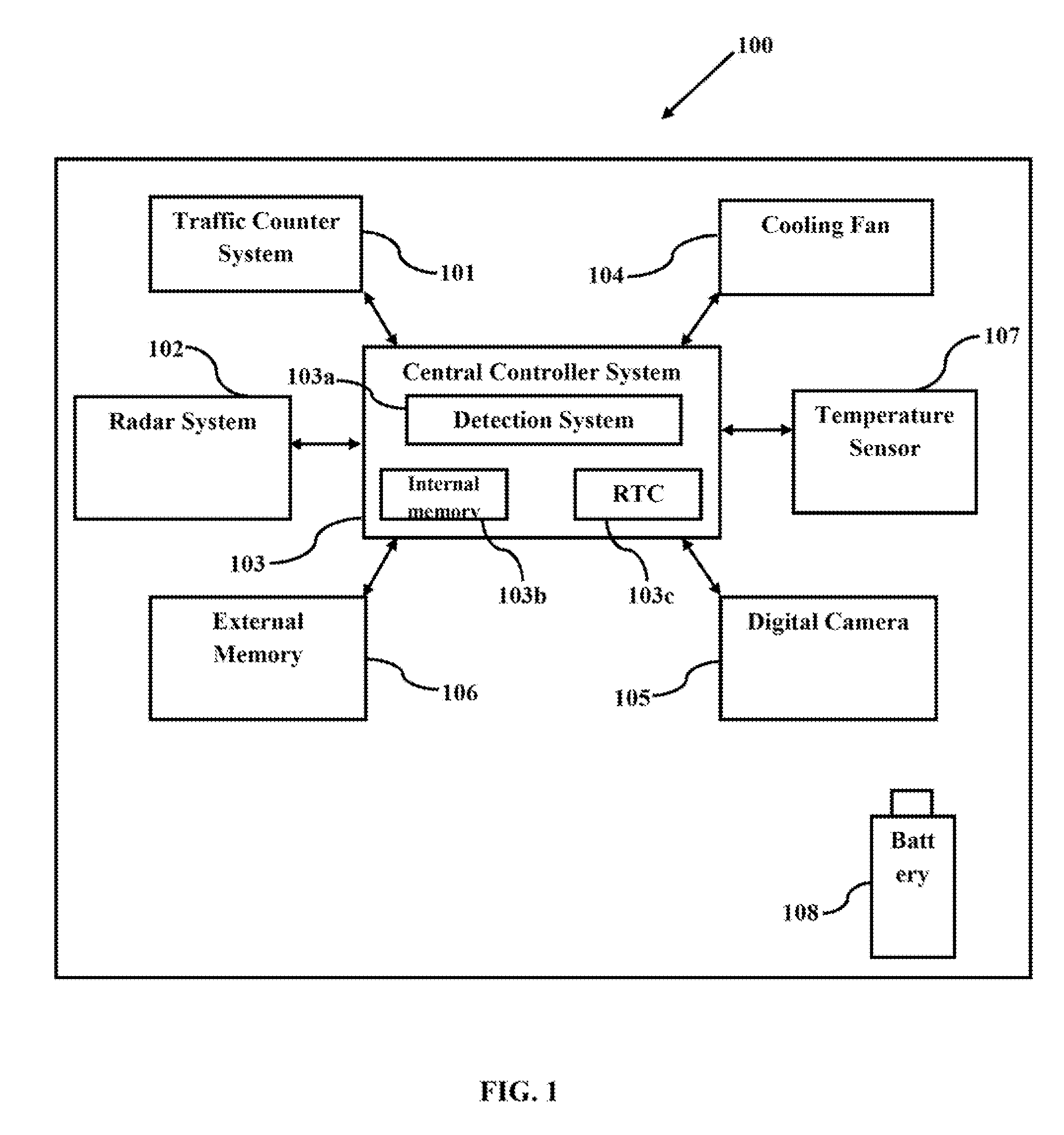
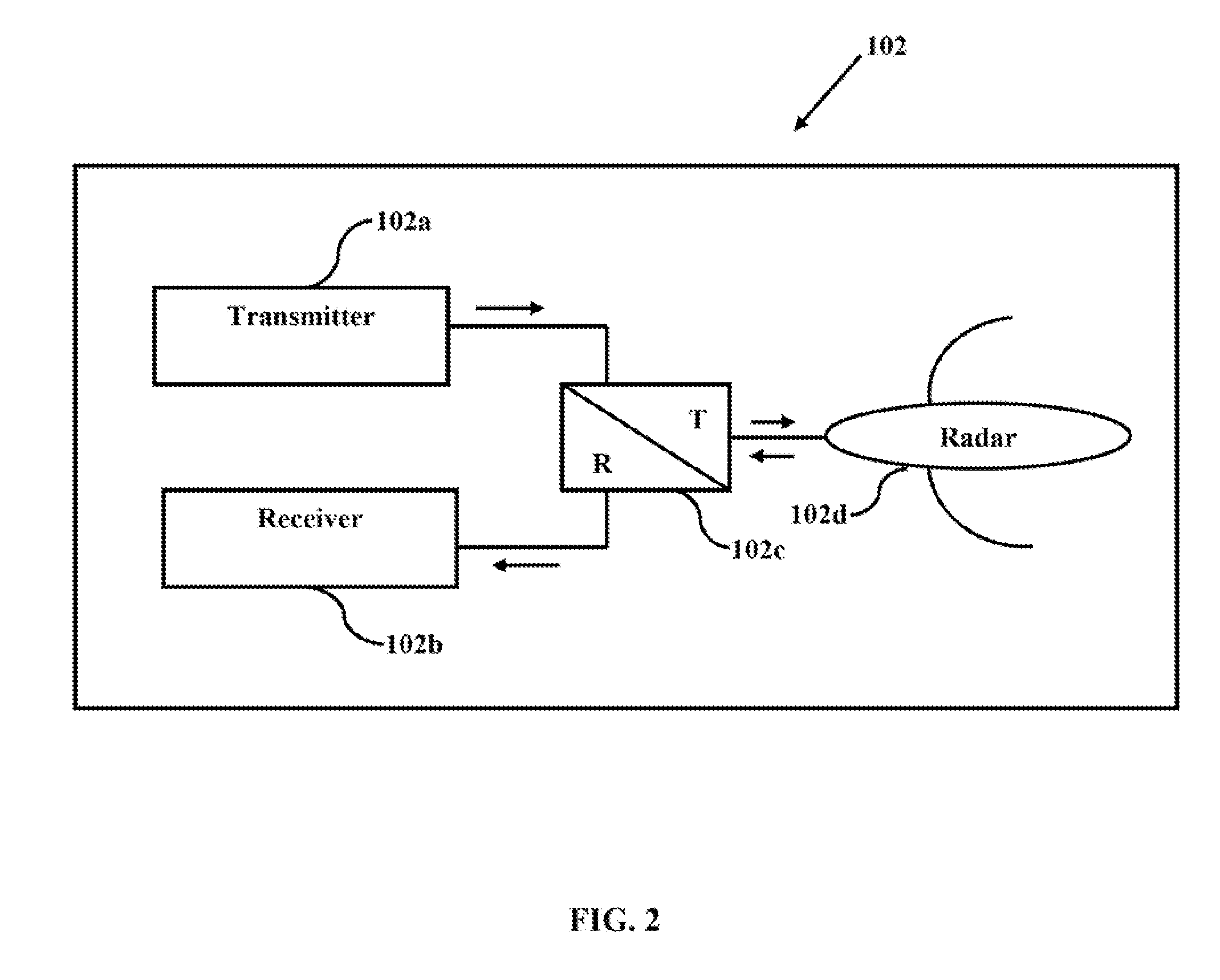
Method and system for detecting moving vehicle speed through athird generation photo radar

a technology of photo radar and moving vehicle, applied in the direction of radio wave reradiation/reflection, measurement device, using reradiation, etc., can solve the problems of inability to determine the speed of all the vehicles moving in different lanes within sight or range of the radar system, system is useless in the streets, roads and high-traffic highways, and regulations have already been changed. to achieve the effect of high resolution

Active Publication Date: 2012-11-15
SEPEHRI AMIRAHMAD +4
View PDF29 Cites 13 Cited by
  • Summary
  • Abstract
  • Description
  • Claims
  • Application Information

AI Technical Summary

Benefits of technology

[0020]According to one embodiment herein, the digital camera captures an image of the plurality moving vehicles after receiving an image capture command from the central controller system, and wherein the digital camera offers high resolution images, zoom lens, a setting for a speed of shooting and a possibility of sequential shooting.
[0022]According to one embodiment herein, the moving vehicle speed detection system further comprises an Uninterruptible power supply (UPS) for avoiding an interruption in an operation during a sudden power outage, and wherein the UPS provides the required electrical power.

Problems solved by technology

The major and common problem of the previously used short range radar systems is that it was impossible to determine the speed of all the vehicles moving in different lanes within a sight or range of the radar system.
Further, the speed detection system would automatically stop resulting in an error message, if two or more vehicles were simultaneously found within a range of the radar system.
Therefore these systems were useless in the streets, roads and high traffic highways.
However, the environmental regulations have been already changed and the radar systems with radar radiations having the maximum output power of 10 mW are allowed to record violations.
The major drawback of this prior art is that the sensors easily get into trouble due to the usage of special invisible coating.
Also the laser lights are useless during the night.
It is found to be difficult in obtaining a proper exposure of the image of a moving vehicle.

Method used


Image

  • Method and system for detecting moving vehicle speed through athird generation photo radar
  • Method and system for detecting moving vehicle speed through athird generation photo radar
  • Method and system for detecting moving vehicle speed through athird generation photo radar

Examples


Embodiment Construction

[0012]The primary object of the embodiments herein is to provide a moving vehicle speed detection system for recording a speed violation.

[0013]Another object of the embodiments herein is to provide a third generation photo radar system for determining a speed and a direction of one or more vehicles moving in different lanes.

[0014]Yet another object of the embodiments herein is to provide a method and a system for calculating a translation of moving vehicles and assigning the determined speed to the vehicle.

[0015]Yet another object of the embodiments herein is to provide a various directional data and graphs thereby facilitating an intelligent management of a traffic speed control.

[0016]These and other objects and advantages of the embodiments herein will become readily apparent from the following detailed description taken in conjunction with the accompanying drawings.

SUMMARY

[0017]The various embodiments herein provide a moving vehicle speed detection system for recording a speed vi...


PUM


Abstract

The various embodiments herein provide a moving vehicle speed detection system for recording the speed violation. The system comprises third generation photo radar for determining an accurate speed of the moving vehicles by measuring a speed and also by measuring the speed with the help of an image processor. The speed of one or more vehicles moving in different lanes within the detection range of the system is accurately measured. The system has a traffic counter system and it can determine an average speed with a very high precision. Generally this system provides the operator with various directorial data and graphs which facilitates an intelligent management of traffic speed control. Also it can determine the accurate speed of any number of vehicles within the range of the system by a third generation photo radar system.

Description

CROSS-REFERINCE TO RELATED APPLICATION[0001]This application claims the priority under 35 USC 119(e) of U.S. Provisional application Ser. No. 61 / 485,777, Filed May 13, 2011, which included by reference herein.BACKGROUND[0002]1. Technical Field[0003]The embodiments herein generally relate to a speed detection system and particularly relate to a moving vehicle speed detection system. The embodiments herein more particularly relate to a method and system for detecting speed of moving vehicles by capturing an image of a moving vehicle through a third generation photo radar system.[0004]2. Description of the Related Art[0005]The system for recording a driving violation using a radar sensor has been marketed since 40 years. After the industrial revolution in 1980s known as information technology revolution, the speed camera detectors were introduced to the world. Since 20 years, these cameras have been common in Europe and they have been installed in the United States for last 10 years. S...

Claims


Application Information

Patent Timeline
IPC IPC(8): G01S13/58G01S13/00
Inventor SEPEHRI, AMIRAHMADREZAEI, AMIR HOSSEINHASHEMI TASHAKORI, SEYED MEHDISHAHMIRZAEI, AMIRSHAMAGHDARI, SAEED SHAMAGHDARI
Owner SEPEHRI AMIRAHMAD
Learn More