Surface light source device, liquid crystal display device, and lens

Active Publication Date: 2012-11-15
PANASONIC CORP
View PDF5 Cites 20 Cited by
  • Summary
  • Abstract
  • Description
  • Claims
  • Application Information

AI Technical Summary

Benefits of technology

[0008]The lens in the light source section has a light incident surface on which light from the light emitting diode is incident with an optical axis at a center, and a light exit surface that expands and emits the incident light, and the light incident surface has a continued depressed surface, while the light exit surface has a continued projected surface. The lens performs such that “sag Y” decreases from a maximum value “sag Y0” with an increment of “θi”, where θi is an angle included between a straight line, connecting an arbitrary point on the light exit surface and a base point on the optical axis which corresponds to a position of the light emitting diode, and the optical axis; sag Y is a distance measured in a light axis direction from the base point on the optical axis to the arbitrary point on the light exit surface; and “sag Y0” is a value of sag Y when angle θi is 0 (zero) degree. The light exit surface except a vicinity of the optical axis takes a shape satisfying a relation of 10 degrees<θmin<30 degrees, where θi takes a minimum value, i.e. θmin when curvature C of a micro-section on the light exit surface in a sectional view which includes the optical axis takes a minimum value.
[0009]Moreover, a liquid crystal display device of the present invention includes: a liquid crystal display panel, and a surface light source device which is arranged on a back surface side of this liquid crystal display panel and has a size corresponding to the liquid crystal display panel, and in which the surface light source device includes: a light source section made up of a plurality of light emitting diodes, and lenses that expand light from these light emitting diode; a housing that accommodates this light source section; a diffusion panel arranged between the liquid crystal display panel and the light source; and a reflection sheet that allows light, emitted from the light source section, to be reflected to the diffusion panel side, wherein the light source section is configured such that plural lenses are arranged by being arrayed in a central section, the lens in the light source section has a light incident surface on which light from the light emitting diode is incident with an optical axis at a center, and a light exit surface that expands and emit

Problems solved by technology

Although the use of the large number of light emitting diodes can give uniform brightness on the surface of the surface light source devi

Method used


Image

  • Surface light source device, liquid crystal display device, and lens
  • Surface light source device, liquid crystal display device, and lens
  • Surface light source device, liquid crystal display device, and lens

Examples


Embodiment Construction

[0029]In the following, a surface light source device and a liquid crystal display device using the surface light source device are described with reference to the drawings.

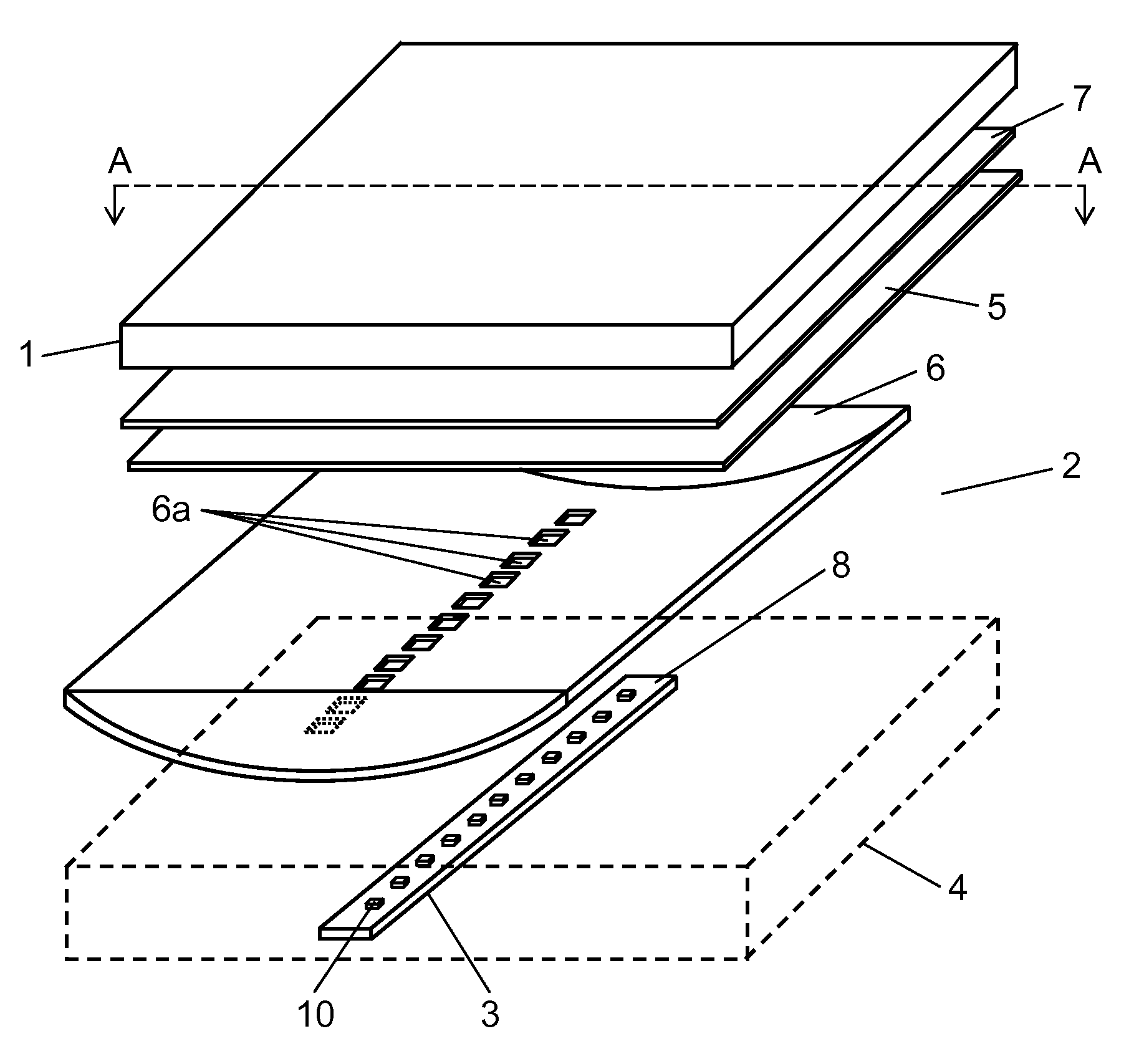
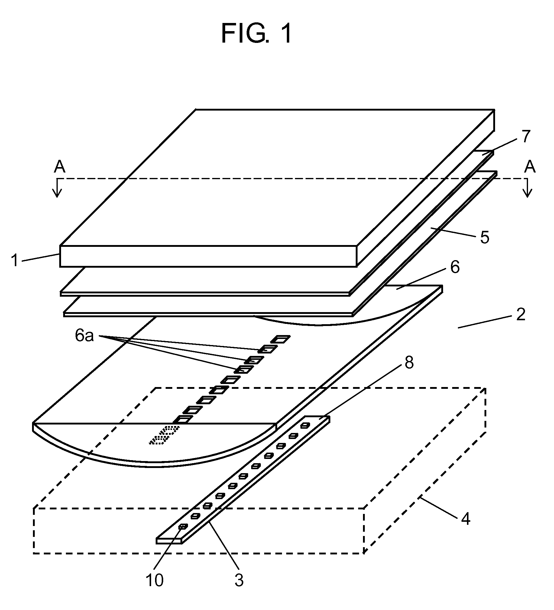
[0030]FIG. 1 is an exploded perspective view showing a schematic configuration of the whole of a liquid crystal display device using a surface light source device according to an embodiment, and FIG. 2 is a sectional view cut along line A-A of FIG. 1.

[0031]As shown in FIGS. 1 and 2, the liquid crystal display device is made up of transmission liquid crystal display panel 1 in the shape of a rectangular flat plate, and surface light source device 2 in a rectangular parallelepiped shape which is arranged on a back surface side of this liquid crystal display panel 1 and has a size corresponding to liquid crystal display panel 1.

[0032]Surface light source device 2 includes: light source section 3 linearly arranged along a direction of a long side of liquid crystal display panel 1 so as to be opposed to a central sect...


PUM


Abstract

The present invention relates to a surface light source, including a light source section made up of plural light emitting diodes and lenses that expand light from these light emitting diodes. The lens in the light source section has a light incident surface on which light from the light emitting diode is incident with an optical axis at a center, and a light exit surface that expands and emits the incident light. The light incident surface has a continued depressed surface, while the light exit surface has a continued projected surface. The lens performs such that “sag Y” decreases from a maximum value “sag Y0” with an increment of “θi”, where θi is an angle included between a straight line, connecting an arbitrary point on the light exit surface and a base point on the optical axis which corresponds to a position of the light emitting diode, and the optical axis; sag Y is a distance measured in a light axis direction from the base point on the optical axis to the arbitrary point on the light exit surface; and “sag Y0” is a value of sag Y when angle θi is 0 (zero) degree, and wherein the light exit surface except a vicinity of the optical axis takes a shape satisfying a relation of 10 degrees<θmin<30 degrees, where θi takes a minimum value, i.e. θmin when curvature C of a micro-section on the light exit surface in a sectional view which includes the optical axis takes a minimum value.

Description

TECHNICAL FIELD[0001]The present invention relates to a surface light source device using a lens that widens directivity of a light source such as a light emitting diode, a liquid crystal display device, and a lens.BACKGROUND ART[0002]In a surface light source device of a conventional large-sized liquid crystal display device, a large number of cold-cathode tubes have been arranged immediately under a liquid crystal panel, and these cold-cathode tubes have been used along with members such as a diffusion panel and a reflection sheet. In recent years, the light emitting diode has been used as a light source of the surface light source device. The light emitting diode has recently been improved in efficiency, and expected as a light source with small consumption power to replace a fluorescent. Further, as for the light source for a liquid crystal display device, the brightness of the light emitting diode can be controlled in accordance with a picture, thereby to reduce power consumpti...

Claims


Application Information

Patent Timeline
IPC IPC(8): G02F1/1335F21V5/04H01L33/58
CPCF21V5/04F21Y2101/02G02B19/0066G02F2001/133607G02F1/133603G02F1/133605G02B19/0014F21Y2115/10G02F1/133607
Inventor MATSUKI, DAIZABUROIIYAMA, TOMOKOKASANO, MASAHIRO
Owner PANASONIC CORP
Why Eureka
Try Eureka