
Close loop method for measuring head SNR and media SNR

a closed loop, head snr technology, applied in the direction of magnetic recording, data recording, instruments, etc., can solve the problems of random shift of read back signal peaks, intrinsic media noise increases with increasing linear recording density, and it is more and more difficult to quickly and accurately position the read/write transducer over the desired information tracks on the disk. to achieve the effect of improving the measurement accuracy of the head snr

Inactive Publication Date: 2012-11-15
SAE MAGNETICS (HK) LTD
View PDF1 Cites 4 Cited by
  • Summary
  • Abstract
  • Description
  • Claims
  • Application Information

AI Technical Summary

Benefits of technology

[0009]One objective of the present invention is to provide a close loop method for measuring head SNR for a storage device. It can make fair condition between signal and noise measurement, thereby improving the measurement accuracy for the head SNR.
[0010]Another objective of the present invention is to provide a close loop method for measuring media SNR for a storage device. It can make fair condition between signal and noise measurement, thereby improving the measurement accuracy for the head SNR.

Problems solved by technology

As track density increases, it becomes more and more difficult to quickly and accurately position the read / write transducer over the desired information tracks on the disk.
In magnetic recording disk drives, where the magnetic recording media on the disks is a granular metal alloy, such as a CoPt alloy, the intrinsic media noise increases with increasing linear recording density.
Media noise arises from irregularities in the recorded magnetic transitions and results in random shifts of the read back signal peaks.
Higher media noise leads to higher bit error rates.

Method used


Image

  • Close loop method for measuring head SNR and media SNR
  • Close loop method for measuring head SNR and media SNR
  • Close loop method for measuring head SNR and media SNR

Examples


Embodiment Construction

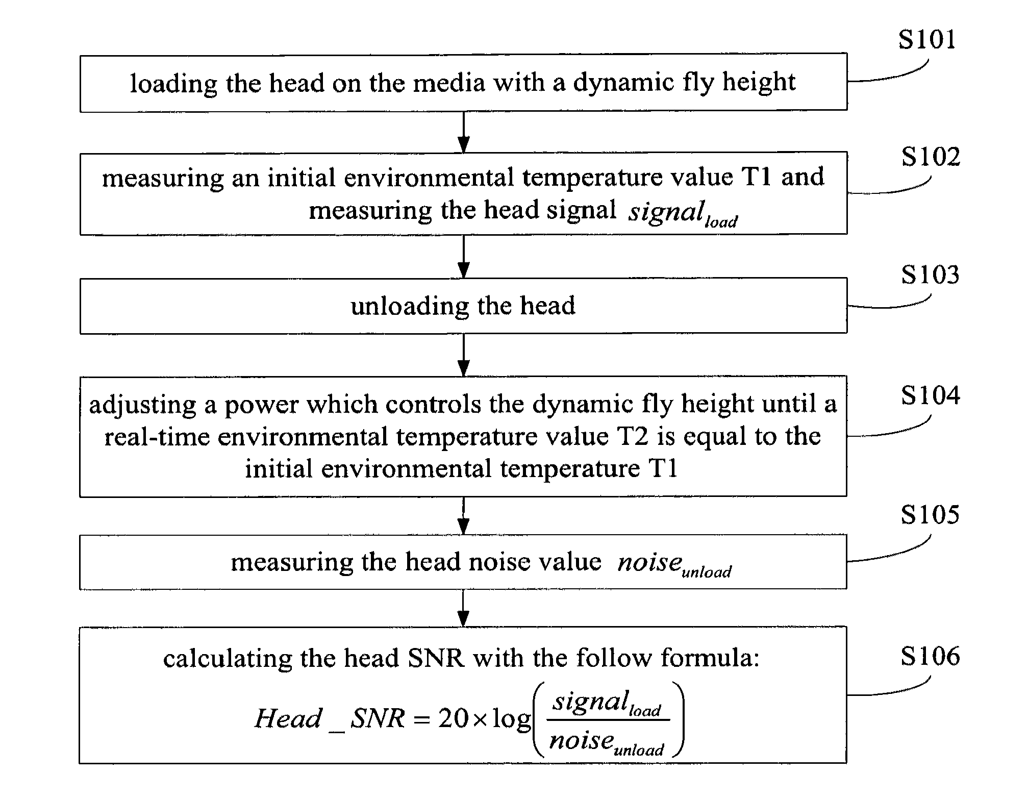
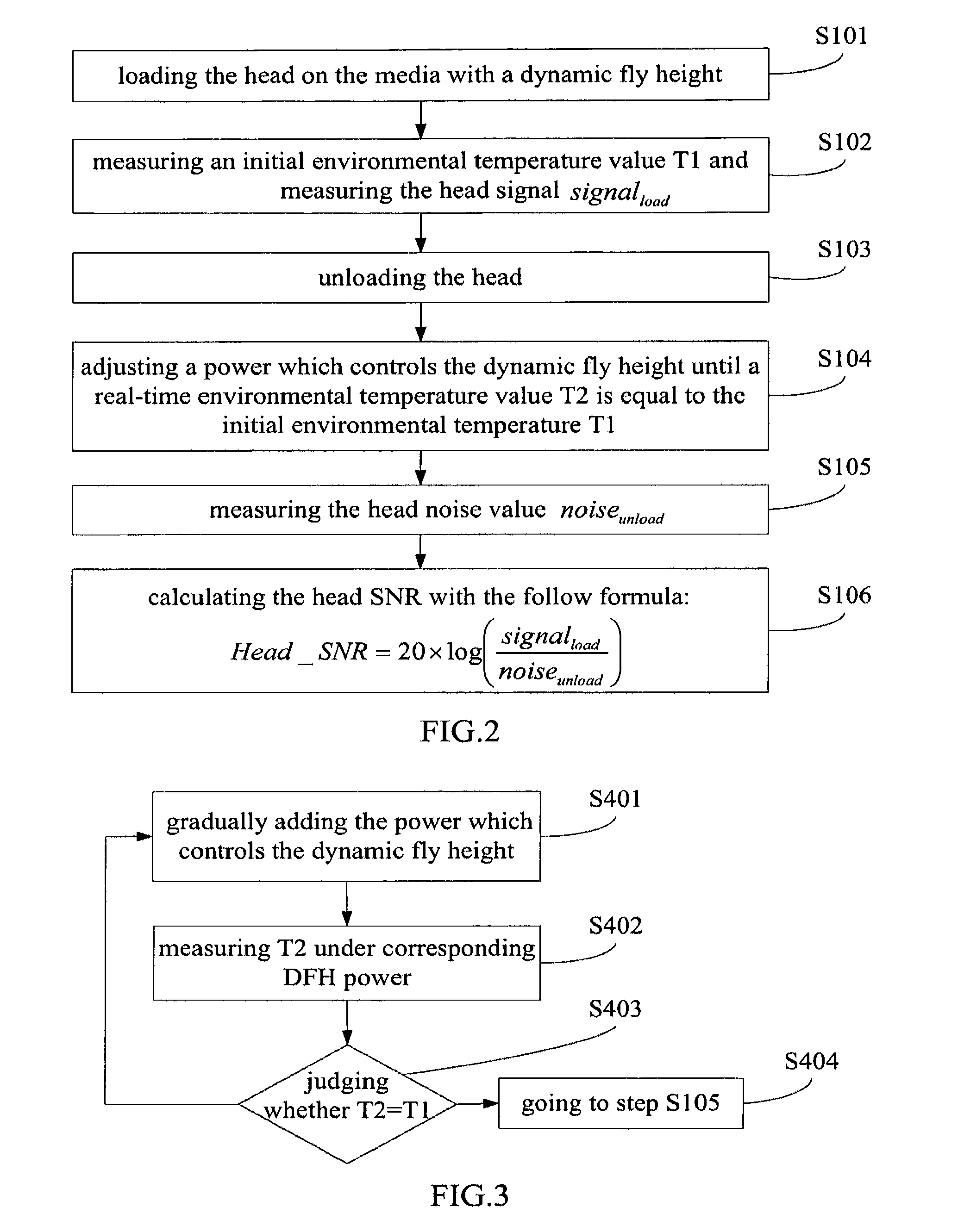
[0028]Various preferred embodiments of the invention will now be described with reference to the figures, wherein like reference numerals designate similar parts throughout the various views. As indicated above, for a storage device comprising a storage media and a head for writing to and / or reading data from the media, the invention is directed to a close loop method for measuring head SNR, it tries to “control” the environmental temperature during unload noise measurement that close to actual case. An initial environmental temperature T1 is measured for comparison when head signal signalload measuring, then the DFH power is adjusting during unload case to affect the real-time environmental temperature until the real-time environmental temperature T2 is equal to the initial environmental temperature T1, thereby the noise measurement can be carried out with fair condition, and a reliable and accurate head SNR can be obtained. Furthermore a reliable and accurate media SNR also can be...


PUM

PropertyMeasurementUnit
dynamic fly heightaaaaaaaaaa
temperatureaaaaaaaaaa
temperature T1aaaaaaaaaa

Abstract

A close loop method for measuring head SNR, for a storage device comprising a storage media and a head, comprising steps of: (a) loading the head on the media with a dynamic fly height; (b) measuring an initial environmental temperature value Ti and measuring the head signal signalload; (c) unloading the head; (d) adjusting a power which controls the dynamic fly height until a real-time environmental temperature value T2 is equal to the initial environmental temperature T1; (e) measuring the head noise value noiseunload, (f) calculating the head SNR with the follow equation:Head_SNR=20×log(signalloadnoiseunload).The method of the present invention can obtain a fair condition between the signal and noise measurement, thereby a reliable and accurate head SNR can be obtain. The present invention also provides a close loop method for measuring media SNR.

Description

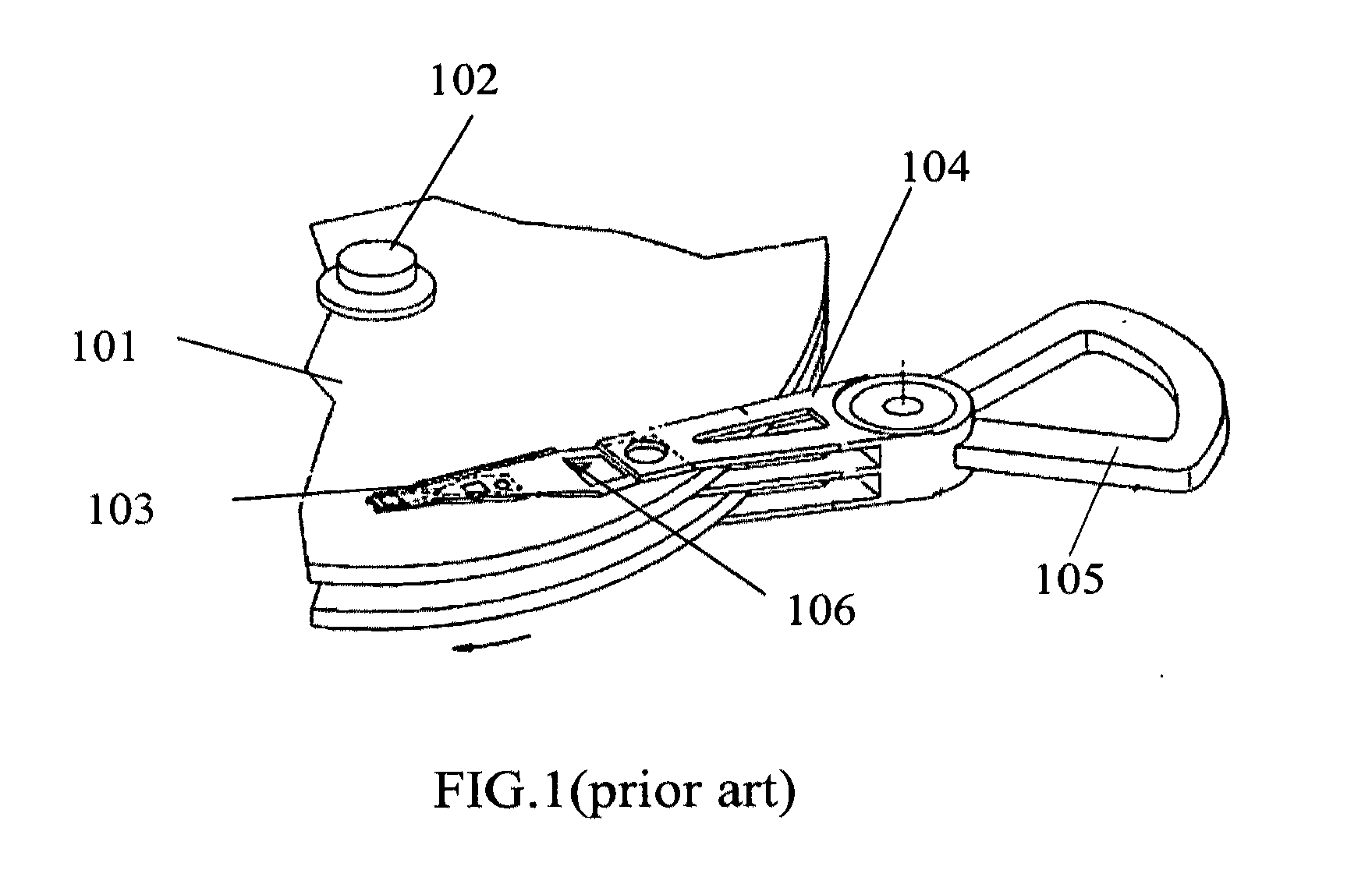
FIELD OF THE INVENTION[0001]The present invention relates to methods for testing the performance of storage devices such as disk drives, and more particularly to a close loop method for measuring head SNR (signal to noise ratio) and media SNR.BACKGROUND OF THE INVENTION[0002]Disk drives are information storage devices that use magnetic media to store data and a movable read / write transducer positioned over the magnetic media to selectively read data from and write data to the magnetic media.[0003]To pursue more accurate reading and writing performance, disk drive manufacturers have continued to develop higher capacity disk drives by, for example, increasing the recording and reproducing density of the information tracks on the disks by using a narrower track width and / or a narrower track pitch. As track density increases, it becomes more and more difficult to quickly and accurately position the read / write transducer over the desired information tracks on the disk. One approach that ...

Claims


Application Information

Patent Timeline
Patent Type & Authority Applications(United States)
IPC IPC(8): G11B21/12
CPCG11B19/048G11B5/607
Inventor LUENG, CHIUMINGLEE, MANKITKWAN, WANYINLEUNG, CHEUKWINGDING, JURENNI, RONGKWANG
Owner SAE MAGNETICS (HK) LTD
Learn More