Thin flat panel LED luminaire

a technology of led luminaires and flat panels, applied in lighting and heating apparatus, instruments, lighting support devices, etc., can solve problems such as increased manufacturing complexity, increased thickness of luminaires, and eye discomfort, and achieve the effect of simple structur

Active Publication Date: 2012-11-15
KUNSHAN CHENGTAI ELECTRIC
View PDF1 Cites 44 Cited by
  • Summary
  • Abstract
  • Description
  • Claims
  • Application Information

AI Technical Summary

Benefits of technology

[0008]In its most general aspect, the invention provides a very thin LED flat luminaire having a simple structure that provides uniform light distribution without glare and visually comfortable lighting. The luminaire generally includes a flat baseboard, a flat reflection panel, a flat acrylic panel, a diffusion panel, a bar with multiple light emitting diodes inlaid in the bar (“LED bar”) and an aluminum encasement frame.
[0010]In another aspect, the acrylic panel is printed with black dots in a mesh-like pattern on one side. The size of the dots and the thickness of the mesh connecting the dots is larger, resulting in a less dense pattern farther away from the LED light bar that couples more light from the reflection panel into the acrylic panel farther away from the LED light bar; the size of the dots is smaller, as is the thickness of the mesh connecting the dots closer to the LED bar, resulting in a denser pattern that couples less light from the reflection panel into the acrylic panel closer to the LED bar. This mesh-like pattern thus provides for a uniform transmission of light across the area of the acrylic panel into a diffusion panel for illuminating a space. The printed pattern is determined by the shape and size of the luminaire, area of the light emitting surface, and wattage of the light emitting diodes.
[0012]In yet another aspect, the LED bar is positioned to emit light to the edge of the flat reflection panel. The flat reflection panel then reflects the light to the acrylic panel. The acrylic panel has a mesh-like pattern of dots across the face of the acrylic panel, the density of the dots and mesh being adjusted in such a manner that the light transmitted by the reflection panel into the acrylic panel has been filtered for uniform evenness through the acrylic panel. Thus, the intensity of the light being emitted by the acrylic panel is relatively uniform across its face. Once the light is filtered through the acrylic panel, the light passes through the diffusion panel which is, in one aspect, an optical polypropylene material that has been treated to provide a magnifying effect. The diffusion panel may further amplify and distribute the light uniformly to the space to be illuminated, resulting in a soft and warm light which is comfortable to the human eye.
[0014]In yet another aspect, the present invention includes a thin LED flat luminaire, comprising: a LED bar having at least one light emitting diode disposed thereon; an optical stack having an edge that abuts the LED bar, including, from top to bottom, a flat baseboard, a flat reflection panel for receiving light from the LED bar, a flat acrylic panel having a top surface and a bottom surface, the top surface facing the flat reflection panel, the top surface having a mask pattern printed thereon, the mask pattern for filtering light transmitted from the flat reflection panel into the flat acrylic panel for providing a uniform transmission of the light from the acrylic panel across the bottom surface of the flat acrylic panel, and a flat diffusion panel configured to receive the light from the bottom surface of the flat acrylic panel and emit the light into a space to be illuminated.
[0016]In still another aspect, the mask pattern is printed with meshing dots, the printed pattern of meshing dots being less dense farther from the LED bar light source and more dense closer to the LED light source so as to selectively filter more light closer to the LED light and less light father from the LED light source to provide for uniform transmission of light from the acrylic panel across the bottom surface of the flat acrylic panel.

Problems solved by technology

This results in glare which may be uncomfortable to the eyes when the LED light source is looked at directly.
However, the usage of such a structure results in increased complexity of manufacture, and increased thickness of the luminaire.

Method used


Image

  • Thin flat panel LED luminaire
  • Thin flat panel LED luminaire
  • Thin flat panel LED luminaire

Examples


Embodiment Construction

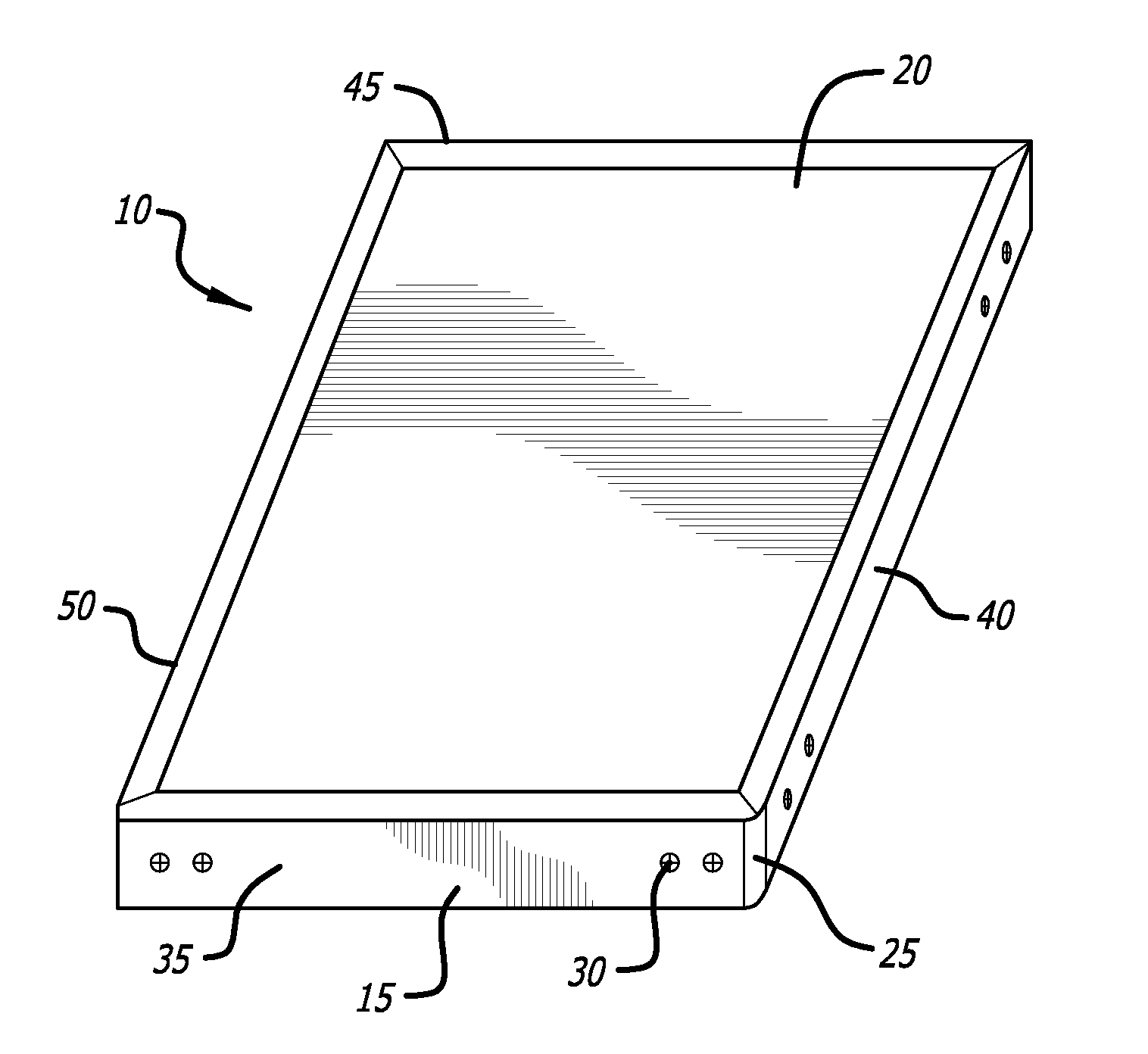
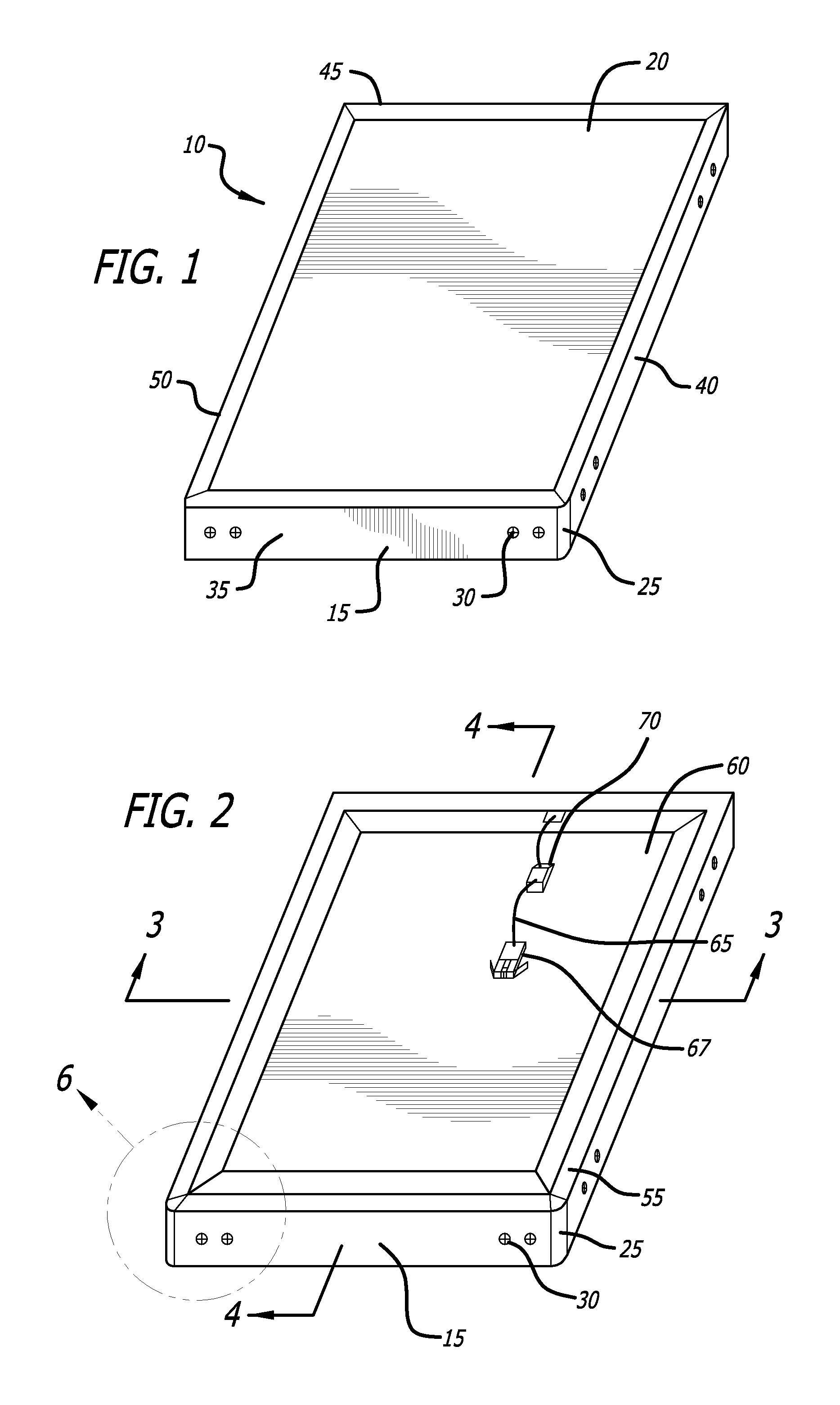
[0030]Referring now to the drawings in detail, in which like reference numerals indicate like or corresponding elements among the several figures, there is shown in FIG. 1 an exemplary thin flat luminaire constructed in accordance with principles of the present invention.

[0031]Thin flat luminaires of the type illustrated in FIG. 1 are useful in providing light in a more efficient manner than can be accomplished using prior art florescent fixtures. Such fixtures are commonly used in public spaces, and may take the form of square or rectangular fixtures. Common sizes of such fixtures are four feet by two feet, and two feet by two feet. Other sizes and shapes are also possible.

[0032]Light Emitting Diodes, or LEDs, are highly efficient sources of light whose mean time between replacement is also significantly greater than florescent or incandescent light sources. LEDs however, are typically relatively small in size, and thus provide light that is relatively intense and focused within a ...


PUM


Abstract

The invention described herein is a very thin flat panel LED luminaire, including a flat baseboard, a flat reflection panel, a flat acrylic panel, a flat diffusion panel, LED bar, and aluminum encasement frame which combines with the baseboard to form the chassis for the luminaire. The LED bar is placed along either or both sides of the stack. The acrylic panel is printed with a mesh-like mask pattern of dots in a pattern in which the density of the pattern is decreases the farther away from the LED bar the pattern is, differentially coupling the light from the point source LED bar from the reflection panel into the flat acrylic panel so that illumination across the luminaire is substantially uniform.

Description

CROSS-REFERENCES TO RELATED APPLICATIONS[0001]This application claims priority from People's Republic of China Application No. 201120147703.9, filed May 11, 2011, incorporated herein by reference in its entirety.BACKGROUND[0002]1. Field of the Invention[0003]The present invention is related to the application of the Light Emitting Diode (“LED”) light source to form a very thin LED flat luminaire for general indoor and outdoor lighting purposes. The luminaire, specifically, reflects and diffuses light from an LED light source which is installed along the edges of the very thin light structure. The light rays are diffused in a manner that provides uniform illumination and color temperature across the luminaire such that there is no irritation from directly looking at the light source.[0004]2. Description of the Related Art[0005]LED technology provides for the manufacture of light fixtures that offer high lumen illumination, low energy consumption, and extended life cycle compared to t...

Claims


Application Information

Patent Timeline
Patent Type & Authority Applications(United States)
IPC IPC(8): F21V13/12F21V21/088
CPCF21S8/04G02B6/0093F21V5/00F21V13/02F21V15/01F21Y2101/02G02B6/0043G02B6/0068G02B6/0076G02B5/0215G02B5/0278G02B6/0051G02B6/0053G02B6/0061F21S8/06F21S4/28F21Y2103/10F21Y2115/10F21V13/08F21V9/20G02B6/0016G02B6/0031G02B6/0055G02B6/0065G02B6/0073F21V3/02F21V7/05F21V17/12F21V23/02F21V23/06
Inventor SHENG, YU LIN
Owner KUNSHAN CHENGTAI ELECTRIC
Why Eureka
Try Eureka