Path recognition device, vehicle, path recognition method, and path recognition program
a technology of path recognition and path recognition, which is applied in the direction of traffic control systems, instruments, and image enhancement, etc., can solve the problem that the stud-shaped lane mark cannot be recognized well, and achieve the effect of reducing the amount of information used in calculation, small calculation amount and high accuracy against nois
- Summary
- Abstract
- Description
- Claims
- Application Information
AI Technical Summary
Benefits of technology
Problems solved by technology
Method used
Image
Examples
first embodiment
Example 2
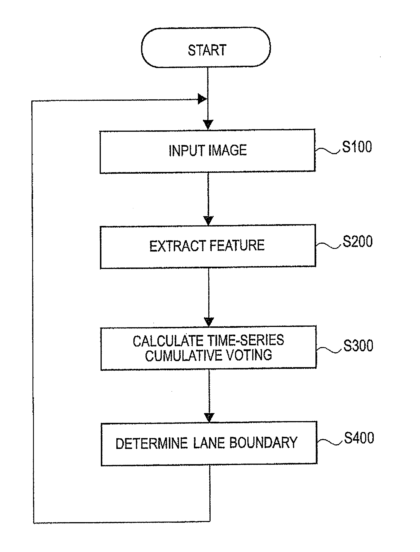
[0075]As a second specific example of the first embodiment, there may be used the following method of generating a time-series cumulative voting feature image while weighting using a forgetting coefficient.
[0076]A cumulative voting feature image generated at the previous time (represented by t−1) is read out, and weighting using a forgetting coefficient (α, 0≦α≦1) is applied to all values in the voting feature image. Further, with regard to each feature point extracted at the present time (represented by t), the vote value to the parameter space (ρ, θ) is calculated. This vote value is added and voted to the read voting feature image, and the generated cumulative voting feature image at the time (t) is stored.
[0077]At that time, when a vote value calculated at a certain time (t) to a certain coordinate (ρ, θ) on the voting feature image is f(ρ, θ, t), a cumulative vote value s(ρ, θ, t) that is an output on a generated cumulative voting feature image can be calculated by the...
second embodiment
[0102]In the above embodiment, although the lane recognition device, method, and program for recognizing the lane boundary expressed by the lane mark have been particularly described, the electronic controller of the lane recognition device may be constituted of only an electronic controller for a stud-shaped lane mark or a combination of the electronic controller for a stud-shaped lane mark and a common electronic controller for a linear lane mark. As the common electronic controller for a linear lane mark, the one described in the Patent Document 1 may be used, for example. Since such a common electronic controller for a linear lane mark is a technique understood by those skilled in the art, the detailed description will be omitted in the present specification.
[0103]As an example of case where the electronic controller for a stud-shaped lane mark and the electronic controller for a linear lane mark are required to be combined, there are a case where the stud-shaped lane mark is pr...
third embodiment
Example 2
[0125]In a second specific example of the third embodiment, first of all, a range that the lateral position can undergo a transition is calculated from the past lane boundary position stored in the linear lane mark feature extraction unit 10-7 and a time-series change of the past lane boundary position. As an example of a specific method, the maximum lateral speed set by the specification of application is assumed, and a transition amount generated from the lateral position at the previous time to the present time may be the transitive range. As another example of a specific method, as in (third embodiment: example 1), estimated lateral speed and Gaussian distribution and trapezoidal distribution set from estimated lateral acceleration are assumed, and a range having a certain probability may be the transitive range.
[0126]Next, one of the values within the above range is selected by being assumed as a correct value, and the origin of the lateral position coordinate of the p...
PUM
 Abstract
Description
Claims
Application Information
 - R&D
- Intellectual Property
- Life Sciences
- Materials
- Tech Scout
- Unparalleled Data Quality
- Higher Quality Content
- 60% Fewer Hallucinations
Browse by: Latest US Patents, China's latest patents, Technical Efficacy Thesaurus, Application Domain, Technology Topic, Popular Technical Reports.
© 2025 PatSnap. All rights reserved.Legal|Privacy policy|Modern Slavery Act Transparency Statement|Sitemap|About US| Contact US: help@patsnap.com


