Optical network system and devices enabling data, diagnosis, and management communications

a network system and optical technology, applied in the field of optical networking systems and optical transceivers, to achieve the effect of eliminating the need for demarcation equipment and more reliable optical communication

Inactive Publication Date: 2012-11-15
II VI DELAWARE INC
View PDF7 Cites 13 Cited by
  • Summary
  • Abstract
  • Description
  • Claims
  • Application Information

AI Technical Summary

Benefits of technology

[0004]Embodiments may include one or more of the following advantages. The presently disclosed optical system and optical transceiver device provide more reliable optical communications comprising users' data as well as diagnosis and management information. The diagnosis and management information are transmitted in optical layer communication channels that are non-intrusive to the user data traffic. The disclosed systems and methods can eliminate the needs for demarcation equipment in some conventional optical network systems.
[0008]In another general aspect, the present specification relates to an optical receiver module for multi-channel communication that includes an optical receiver that can convert an optical signal into an electric signal, wherein the optical signal comprises the user data signal and a diagnostic waveform that is modulated by a management data signal, wherein the user data signal comprises user data in a first communication channel and has a first frequency associated with first communication channel, wherein the first frequency is higher than 1 Gbps, wherein the diagnostic waveform has a second frequency associated with the first communication channel, wherein the second frequency is in a frequency range between about 10 KHz and about 10 MHz, wherein the management data signal has a third frequency specific to the first communication channel, wherein the third frequency is in a frequency range between about 1 KHz and about 100 KHz; and a management diagnostic demodulator that can extract the diagnostic waveform from the electric signal and to extract the diagnostic waveform at the second frequency specific for the first communication channel, and to extract, from the diagnostic waveform, the management data signal and the management data specific for the first communication channel.
[0012]Implementations of the system may include one or more of the following. The third frequency can be in a frequency range between about 1 KHz and about 100 KHz. The amplitude of the diagnostic waveform can be between about 1% and 10% of the amplitude of the user data signal. The optical transmitter module can further include a driver that can drive the optical transmitter in accordance to the user data signal, the diagnostic waveform, and the management data signal. The optical transmitter module can further a first current sink coupled with the optical transmitter, the first current sink that can be modulated by the user data signal, wherein the first optical signal emitted by the optical transmitter is modulated by the first current sink. The optical transmitter module can further a second current sink coupled with the optical transmitter, the second current sink that can be modulated by the diagnostic waveform that is in turn modulated by the management data signal, wherein the first optical signal emitted by the optical transmitter is modulated by the second current sink. The second current sink can include a modulation current that has a constant DC level to eliminate optical power fluctuations in the optical transmitter. The management diagnostic modulator can further include a programmable oscillator that can receive the management data signal to produce a modulation signal that comprises the diagnostic waveform modulated by the management data signal, wherein the management diagnostic modulator is that can send the modulation signal to modulate the second current sink. The management diagnostic modulator can tune the second frequency to the first communication channel in response to a frequency control signal.

Problems solved by technology

As service provides' networks are becoming more complex, reliable services and effective management of the networks have become key challenges for service providers to ensure service level agreement (SLA) and guarantee customer satisfaction.

Method used


Image

  • Optical network system and devices enabling data, diagnosis, and management communications
  • Optical network system and devices enabling data, diagnosis, and management communications
  • Optical network system and devices enabling data, diagnosis, and management communications

Examples


Embodiment Construction

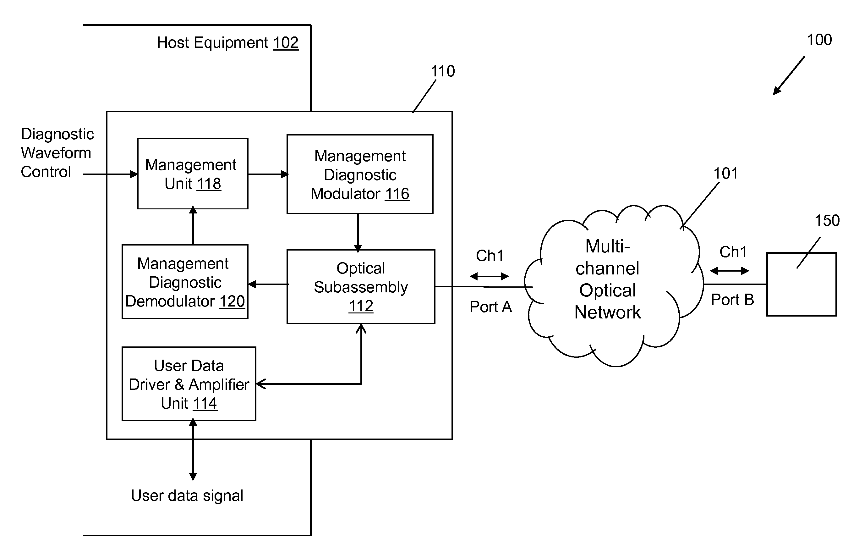
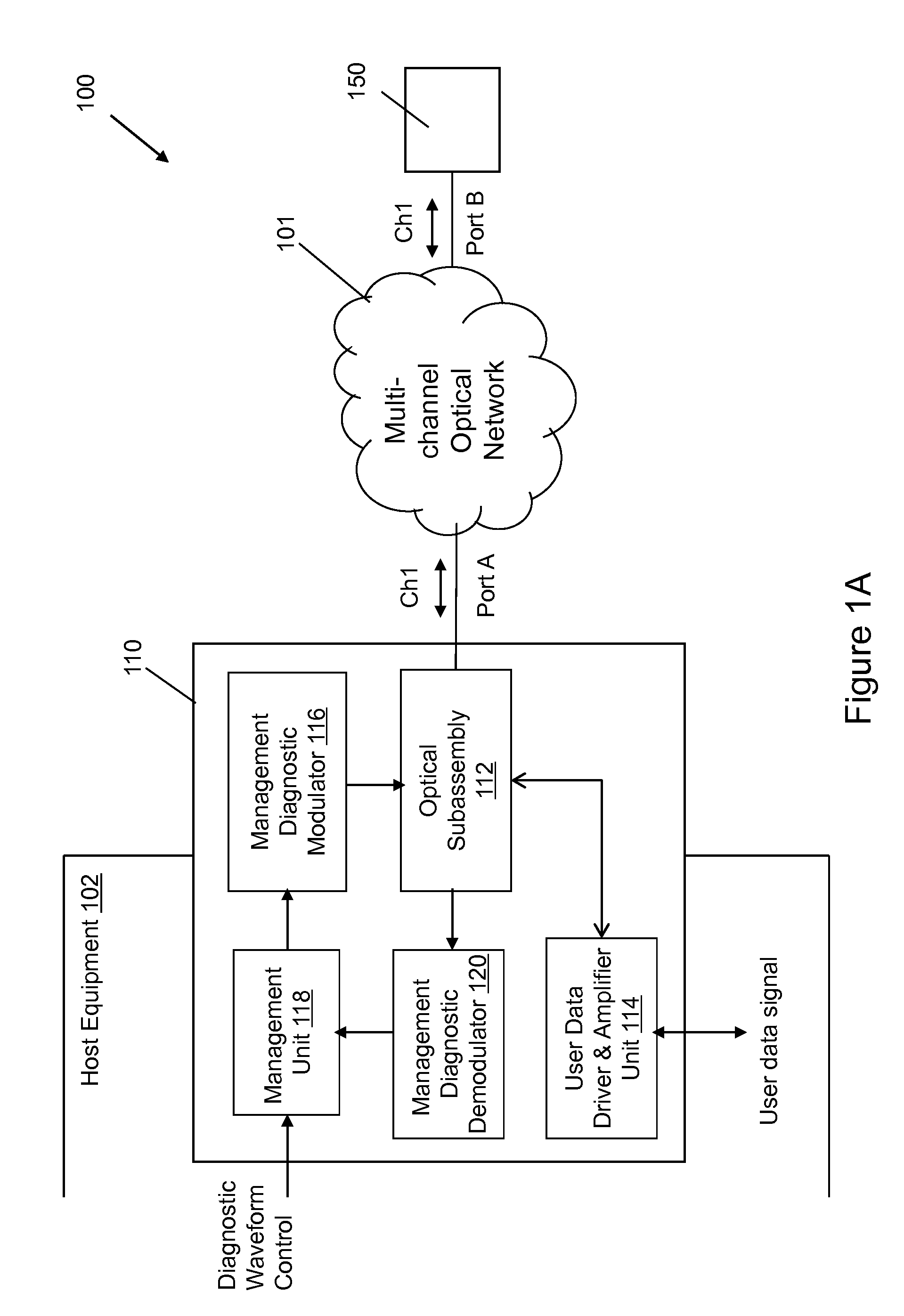
[0024]Referring to FIGS. 1A and 1B, a multi-channel optical network system 100 includes a multi-channel optical network 101 that include plurality of ports for optical communications in multiple channels “Ch1”, “Ch2”. . . “Ch N”. Specifically, Port A and Port B are respectively connected to optical transceivers 110 and 150 for communication in the channel “Ch 1”.

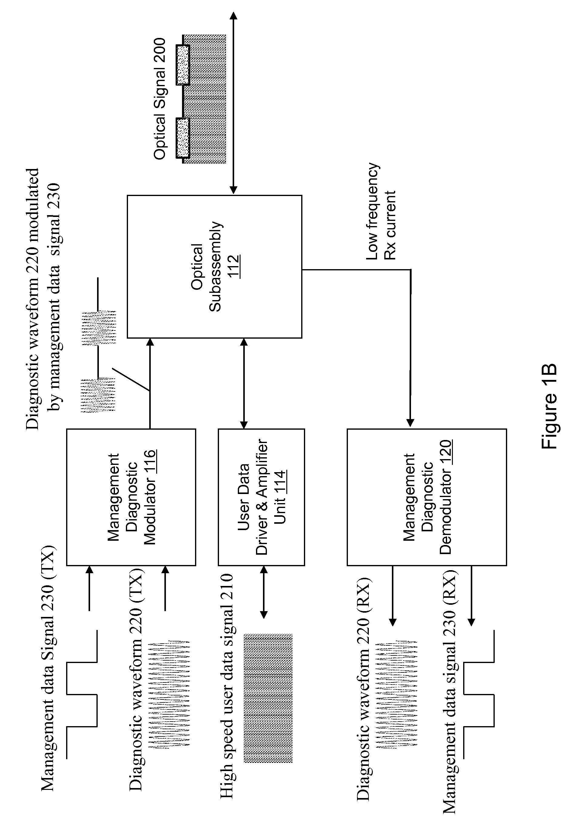
[0025]The optical transceiver 110 includes an optical subassembly 112, a data driver & amplifier unit 114, a management diagnostic modulator 116, a management diagnostic demodulator 120, and a management unit 118. The optical subassembly 112 is configured to transmit and receive optical signals. The data diver & amplifier unit 114 is configured to transmit and receive a user data signal from host equipment 102. In the present specification, the term “user data” refers to the data that carries information to be communicated between users at different points in an optical communication network. For example, “user data” can be ...


PUM


Abstract

An optical transmitter module includes an optical transmitter configured to emit a first optical signal that includes a user data signal having a first frequency and comprising user data associated with the first communication channel. A management diagnostic modulator can superimpose a diagnostic waveform to the user data signal. The diagnostic waveform has a second frequency associated with the first communication channel, wherein the second frequency is in a frequency range between about 10 KHz and about 10 MHz. A management unit can modulate the diagnostic waveform by a management data signal at a third frequency associated with the first communication channel. The management data signal includes management data for digital diagnostic monitoring signals (DDM) and the control of the first optical transceiver module.

Description

BACKGROUND OF THE INVENTION[0001]The present disclosure relates to optical networking systems and optical transceivers used in the optical networking systems.[0002]As voice over Internet Protocol (VoIP) and Internet Protocol television (IPTV) grow in popularity, an increasing number of users desire to have access to these services from their premises. Similarly, businesses now require more bandwidth available to their premises with necessary quality of service. To meet these needs, network carriers are building optical access networks with different network topologies such as fiber-to-the-premises, fiber-to-the-node, or fiber-to-the-building with many different access transport solutions.[0003]As service provides' networks are becoming more complex, reliable services and effective management of the networks have become key challenges for service providers to ensure service level agreement (SLA) and guarantee customer satisfaction.SUMMARY OF THE INVENTION[0004]Embodiments may include...

Claims


Application Information

Patent Timeline
Patent Type & Authority Applications(United States)
IPC IPC(8): H04B17/00
CPCH04B10/0775H04B2210/074H04B10/0779
Inventor LI, WEN
Owner II VI DELAWARE INC
Why Eureka
Try Eureka